
Double Arc Edge Cable Tray Making Machine 50-300mm
Fully automatic cable tray making machine for 50–300 mm trays with a double arc side edge — smoother installation, stiffer profile. Runs 0.5–1.5 mm Q235 or galvanized strip at 5–12 m/min through a 5-ton hydraulic decoiler, 11-roller servo feeder, 180T Hebei press, and a 28-pass forming mill on φ50 mm shafts.
Looking for a cable tray making machine that turns coils into finished trays without a single manual touch? This 50-300mm line does exactly that. Moreover, it puts a double arc edge on every side wall, so installers never scrape their hands on sharp lips during overhead work. From decoiling to run-out, the whole process is servo-timed, punch-synced and roll-formed in one pass.
The line is built around a 180-tonne mechanical press, a 28-pass forming mill on φ50 mm shafts, and a 5-tonne hydraulic decoiler. As a result, it holds ±1.5 mm on length and width while running 0.5–1.5 mm steel at 5–12 m/min. In short, it is designed for factories that want consistent, safe-edged trays in the widest range of standard sizes.
Why the Double Arc Edge Matters
Most tray lines fold the side wall into a single sharp flange. However, the double arc edge rolls that flange into two smooth curves, and it changes three things on the jobsite:
- Safer handling. Electricians grip the edge dozens of times per shift. Consequently, a rolled-under double arc removes cuts and glove wear.
- Higher torsional stiffness. Two curves stiffen the side wall more than a single fold. Therefore, the tray resists twist over long cable runs.
- Cleaner look on exposed runs. In finished spaces such as data halls or retail ceilings, the rounded lip photographs and installs cleaner than a raw flange.
In other words, you get a tray that is safer to install, stronger in service and more presentable when the ceiling stays open.
Line at a Glance
Six Modules, One Continuous Flow
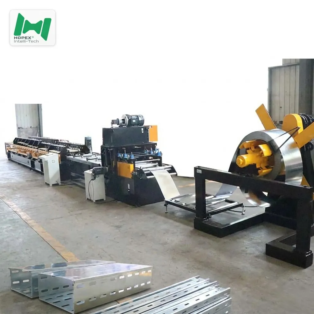
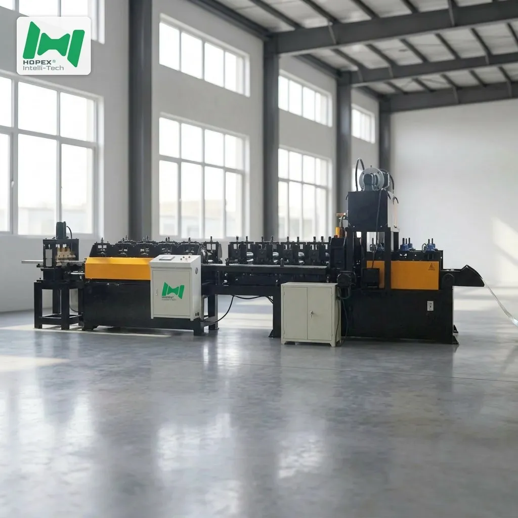
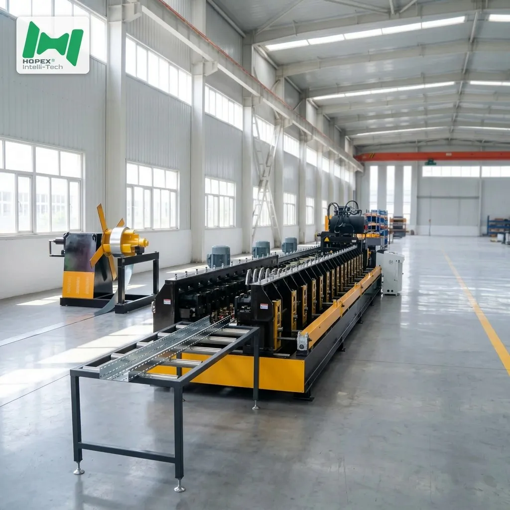
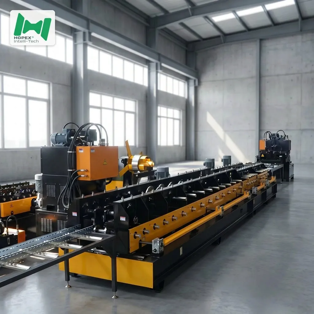
The 50-300mm line breaks down into six modules. Each one has a defined job; together, they form a straight-line process that needs only a coil at the front and a stacker at the back.
1. Hydraulic Decoiler (5-Ton)
The coil sits on a hydraulic expanding mandrel with electric drive. Inner diameter adjusts from φ460 to φ520 mm, and the outer diameter accepts up to φ1500 mm. Because expansion is hydraulic, coil changes take minutes instead of ten-minute manual tightening cycles.
2. Leveling · Servo Feeding · Cut-Off Combo
This is the brain of the front end. It carries 11 leveling rollers (3 upper, 4 lower, plus a clamp pair at each end) on φ100 mm rollers driven by a 4 kW motor. Servo pitch feeding delivers the strip to the press with the accuracy the punch tooling needs — and the cut-off happens in the same block, so the sheared blank goes straight into forming.
3. Punching Press — 180 T Mechanical
A Hebei-made 180-tonne mechanical press stamps the ventilation or connection hole pattern via a customer-defined die. In addition, a mechanical press is the right choice at 1.5 mm gauge with dense hole layouts, because inline hydraulic punching struggles to keep pattern density and edge quality at production speed.
4. Custom Die
The die is the swappable heart of the punching station. Consequently, changing the hole pattern, spacing or shape only means switching the die — the rest of the line stays the same. Common patterns include slotted vents, round holes and end connection holes.
5. Roll Forming Mill — 28 Passes
After punching, the blank enters the mill. Twenty-eight forming passes on φ50 mm 45# steel shafts progressively roll the double arc edge and finish the tray profile. Two 5.5 kW main motors drive the chain, while two 1.5 kW motors handle automatic open/close for width changes. Rollers are Cr12 tool steel, hardened for long service.
6. High-Speed Table + Run-Out
A 3-metre powered roller table (1.5 kW, electric open/close) transports the freshly formed tray from the mill. Then, a 3-metre passive idler run-out carries the finished piece to the operator or stacker.
What the Line Runs
The output envelope is the promise you make to your buyers. Here is what this machine delivers off the run-out table.
In practice, 50 – 300 mm base width covers the majority of standard trays on commercial and light-industrial projects. Consequently, one line handles almost the full catalogue a fabricator lists in a typical tender.
Component Brands You Can Verify
Sourced parts are named, not hidden. Therefore, spares are easy to find worldwide.
Note: brands listed cover main equipment. Auxiliary parts may vary by production batch; the substitution list is disclosed at order confirmation.
Where Double Arc Trays Fit Best
Because the edge is rolled smooth and the profile is stiff, this line’s output ships into a broad set of projects:
Line Comparison — Standard Flange vs. Double Arc
If your buyers are asking why they should specify a double arc tray over a plain-flange one, this side-by-side answers it.
Common Questions
Is this line fully automatic?
Yes. Once a coil is loaded and the die is set, the line runs coil-to-finished-tray on its own. Furthermore, the servo feeder synchronises with the press, and the cut-off is integrated — so there is no manual re-positioning between punching and forming.
Can I change the hole pattern later?
Yes. The hole pattern lives entirely in the custom die. Therefore, swapping to a different vent layout or connection-hole pitch is a die change, not a line change.
What steel does the line handle?
Q235 cold-rolled and galvanized strip from 0.5 to 1.5 mm thick. In addition, the strip width band of 150–450 mm covers all base widths from 50 to 300 mm.
How fast does it run?
5 to 12 metres per minute, depending on hole count per tray and the die’s stroke rhythm. Denser hole patterns naturally slow the press cycle.
Why 28 forming passes for a 50 mm-tall tray?
The double arc side edge is a compound curve. It takes more stations than a single-fold flange to roll cleanly without stress marks on the outside surface. Consequently, 28 passes is what delivers a consistent arc on both sides at production speed.
What is the changeover time between widths?
Width change is handled by the automatic open/close motors on the mill (1.5 kW × 2). As a result, moving between 50, 100, 150, 200 and 300 mm trays is a preset call on the HMI rather than a manual re-shimming job.
What’s the total footprint?
The line measures 30 m long × 2.5 m wide × 2.2 m high. Additionally, it draws about 50 kW installed on 380 V / 50 Hz / 3-phase, with a compressed-air supply of 0.5 m³/min at up to 0.7 MPa.
Are motors rated for hazardous areas?
Yes. Motors are supplied to IP55 protection and ExdIICT4 explosion-proof rating, suitable for the atmospheres typical of a tray-forming workshop.
Bottom Line
If your product plan calls for 50 – 300 mm cable trays with a safe, rounded double arc side edge, this line is built for the job. It combines a 5-ton hydraulic decoiler, servo leveling and feeding, a 180-tonne press with your custom die, and a 28-pass forming mill on φ50 mm shafts — all inside a 30 × 2.5 × 2.2 m footprint drawing roughly 50 kW.
For engineering drawings, die-pattern intake, or sample tray inspection, contact our project team with your target dimensions, hole layout, steel grade and monthly output. Then we configure the die and mill to your production plan.