
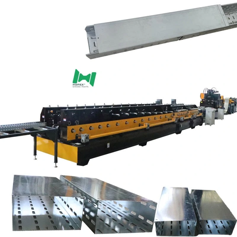
Servo Cable Tray Machine 50-400mm
Precision servo cable tray machine for 50–400 mm × 50–100 mm cable trays across nine standard sizes at ±1 mm tolerance. Runs a full Delta servo ecosystem — Delta inverter, Delta touchscreen HMI, Delta servo motor — on a 26-pass opposing-roller mill with inner-fold or outer-fold small edge selectable at order. Ships native at 400 V / 60 Hz for direct commissioning in North American and South American plants. 7-roller leveler, 26-pass forming, 11 kW hydraulic station, 30 × 2.5 × 2.2 m footprint.
Most cable tray lines mix servo motors from one brand with inverters from another and a PLC from a third. Consequently, troubleshooting a production fault means reading documentation from three different companies. This servo cable tray machine takes a different approach: the inverter, touchscreen HMI and servo motor all come from Delta — one brand, one protocol stack, one service network. Moreover, that single-brand servo ecosystem is what delivers the line’s tight ±1 mm tolerance on both length and width across nine standard finished sizes.
The line handles 0.8–1.5 mm Q235 cold-rolled or galvanized strip at 8–16 m/min, forms the full 50–400 mm × 50–100 mm tray envelope in 26 passes, and ships in 400 V / 60 Hz configuration. In short, it is built for fabricators who want consistent trays and maintainable machinery — not just a long spec sheet.
Why a Single-Brand Servo Ecosystem Matters
Three components govern tray-to-tray consistency on any forming line: the inverter (controls mill speed), the servo motor (controls feeder pitch) and the HMI (where operators set recipes). Furthermore, when all three come from different brands, three things compound over time:
- Protocol friction. Tuning the servo feeder to match mill ramp speed requires mapping between two different parameter sets. Additionally, firmware updates on one component can break tuning presets on the other.
- Fault isolation is slower. A feeding irregularity could be the inverter ramp, the servo gain, or the HMI recipe — and each needs a different diagnostic tool.
- Spare-part sourcing splits. One local Delta dealer serves all three components on this line. In contrast, a mixed-brand line needs relationships with three separate suppliers.
This servo cable tray machine runs Delta inverter + Delta touchscreen HMI + Delta servo motor as a unified ecosystem. As a result, the feeder pitch, mill speed and recipe management all talk the same protocol without an engineering workaround.
Servo Cable Tray Machine at a Glance
The Nine Sizes This Line Covers
The mill produces all nine standard sizes in one setup by combining four width settings and two height settings:
Furthermore, the servo open/close motor on the small-edge station handles width changes from the HMI — no manual shim swaps, no mechanical strip-down between orders.
What Earns the ±1 mm Tolerance
Most cable tray lines specify ±1.5 mm on length and width. This servo cable tray machine holds ±1 mm — half a millimetre tighter. Notably, four engineering decisions work together to make that precision real:
1. Delta Servo Feeder — Pitch Accuracy
The servo feeder delivers the strip to the die at the exact stroke position on every cycle. Furthermore, because the servo motor and inverter share a Delta protocol, gain tuning is a single-screen operation — not a cross-brand parameter map. Consequently, pitch repeatability stays within the tolerance the servo is rated for, not what the integration allows.
2. 26-Pass Progressive Forming
Twenty-six passes means the strip moves from flat to finished profile in small, controlled angular increments. Therefore, spring-back at each station is predictable and compensated by the roller geometry — not absorbed by a large final-station correction.
3. Opposing-Roller Final Forming
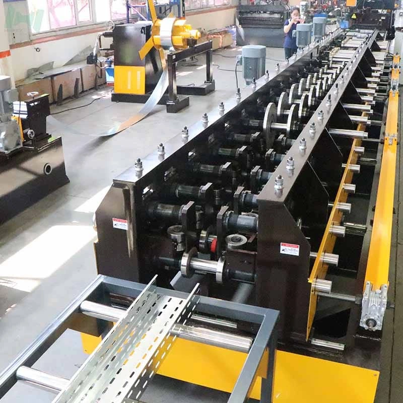
The rear forming section uses opposing rollers — top and bottom rollers pressing from both sides — rather than a single-sided final station. As a result, wall angle is locked in symmetrically, not biased to one side under forming load.
4. 7-Roller Leveler with Lift-Linkage
A strip that enters the die with internal waviness cannot produce ±1 mm length tolerance regardless of servo precision. Consequently, the 7-roller leveler with lift-linkage flattens the strip across seven reverse-bend cycles before it reaches the feeder — removing the coil-set stress that would otherwise create cut-length variation.
Inner-Fold vs Outer-Fold Small Edge — An Engineering Decision
At order time, buyers specify inner-fold or outer-fold for the small edge (7–15 mm). Both options share the same 6-pass small-edge station and the same 5.5 kW + 1.5 kW drive pair. However, the geometry inverts — and that changes the tray’s behaviour in the field:
Furthermore, both options include the small-edge levelling roller that removes punch-induced lift before the strip enters the rear forming section.
Opposing-Roller Final Forming — Why It Matters
Standard forming mills use a single-sided final station: a driven roller on one side and a passive idler on the other. However, this approach biases the forming load to the driven side, and the wall angle on the driven side sets a fraction tighter than the passive side. Consequently, over thousands of pieces the tray profile drifts asymmetrically.
The rear section of this servo cable tray machine uses opposing rollers — top and bottom, both driven — which apply symmetric forming load to both walls simultaneously. As a result:
- Wall angle sets identically on both sides of the tray
- Asymmetric profile drift is eliminated
- The ±1 mm angular tolerance of 90° ± 2° holds without operator adjustment
Additionally, opposing-roller geometry makes the final station less sensitive to strip-thickness variation within the 0.8–1.5 mm band — both walls respond to gauge change equally.
Full Line Walk-Through
The line reads left to right in seven stations:
6-tonne decoiler → 7-roller leveler + servo feeder + punch + cut-off → 3m conveyor → Small-edge forming → Rear mill (opposing rollers) → 3m run-out → 11 kW hydraulic station
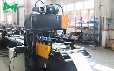
1. Decoiler — 6-Tonne Hydraulic
The coil sits on a hydraulic expanding mandrel with electric drive. Inner diameter opens from φ460 to φ520 mm; outer diameter accepts up to φ1500 mm. Because payoff is electrically driven, strip tension stays controlled at 8–16 m/min.
2. Leveling + Punch + Cut-Off Combo
The 7-roller leveler with lift-linkage flattens the strip. Immediately downstream, the Delta servo feeder (4 kW) delivers it to the die at the exact pitch. Furthermore, punching and cut-off share the same station frame — the die stamps and shears in one stroke, keeping hole-to-cut registration within the ±1 mm tolerance.
3. Small-Edge Forming — 6 Passes
The small-edge station rolls the 7–15 mm rim through six passes. Additionally, it carries the small-edge levelling roller to remove punch-induced lift before the strip enters the rear mill.
4. Rear Forming Mill — Opposing Rollers
The rear section forms the side walls to either 50 or 100 mm and locks the profile via opposing rollers. Main motor: 5.5 kW; open/close motor: 1.5 kW.
5. High-Speed Conveyor — 3-Metre Powered
A 3-metre roller conveyor (1.5 kW, electric open/close) carries the blank from the punch station to the mill. Because it decouples press and mill cycle, a slightly slower forming pass does not hold back the feeder.
6. Run-Out Platform
A 3-metre passive idler run-out carries finished trays for pick-up. Passive discharge keeps surface quality clean.
7. Hydraulic Station — 11 kW / 450 L
An independent 11 kW hydraulic station with a 450 L oil tank feeds the punch, cut-off and all servo actuators. Multiple solenoid valves, an electromagnetic pressure relief and an active cooling system hold oil temperature stable across full-shift running.
Delta Servo Ecosystem — Component by Component
The three components that govern feeding precision all come from one manufacturer:
Note: brands listed cover main equipment. Auxiliary parts may vary by production batch; substitutions are disclosed at order confirmation.
Where the Servo Cable Tray Machine Fits Best
Because this servo cable tray machine delivers ±1 mm tolerance on nine standard sizes with a servo-integrated control architecture, it suits fabricators serving projects where tray geometry is actively checked:
Common Questions
What makes this a “servo” cable tray machine?
Three components: the Delta servo motor that controls feeder pitch, the Delta inverter that controls mill speed, and the Delta HMI that stores width and length recipes. Furthermore, all three share a single Delta protocol, so tuning, diagnostics and recipe management happen on one platform.
Why does this servo cable tray machine hold ±1 mm instead of ±1.5 mm?
For assembled cable tray systems, a ±1 mm tolerance means trays and fittings align without field trimming. Additionally, on structured cabling projects where tray runs are engineered from drawings, ±1.5 mm accumulates into visible misalignment across a 30-metre run. Consequently, specifiers on tight-tolerance projects explicitly call out ±1 mm.
Does the inner-fold or outer-fold small edge affect tolerance?
No. Both options use the same 6-pass small-edge station and the same Delta servo open/close — tolerance is identical. However, inner-fold requires slightly more attention to cover fitment at changeover. Therefore, if in doubt, discuss cover type before specifying edge fold direction.
Can I switch between inner-fold and outer-fold on the same line?
Not without a roller cassette swap — the small-edge station uses a fixed geometry set for the chosen option. Furthermore, the swap is a commissioning-level change, not an operator-level recipe change. Therefore, most buyers specify one option and run it consistently.
What is the 60 Hz configuration?
The line ships natively at 400 V ± 5% / 60 Hz / 3-phase — the standard for industrial plants in the USA, Mexico, most of Central and South America, and parts of the Middle East. Consequently, no transformer modification is needed at the destination.
What is the total footprint and power draw?
30 m long × 2.5 m wide × 2.2 m high, drawing approximately 50 kW installed. Additionally, the dedicated hydraulic station is 11 kW with a 450 L oil tank.
Bottom Line
If your production plan calls for nine standard cable tray sizes at ±1 mm tolerance, on a line where the servo feeder, inverter and HMI speak the same protocol, this servo cable tray machine is the equipment for it. It combines a 6-tonne decoiler, a 7-roller leveler, a Delta servo feeder, inner or outer-fold small-edge forming, 26-pass opposing-roller rear mill, and a Delta-unified control architecture — all inside a 30 × 2.5 × 2.2 m footprint drawing approximately 50 kW, shipping native at 400 V / 60 Hz.
For mill drawings, small-edge option selection, or a Delta ecosystem walk-through on the HMI, contact our engineering team with your target sizes, hole pattern, steel grade and monthly output. Then we configure the die, small-edge rollers and control recipes to your production plan. our production plan. on plan.