
Cable Tray Forming Line Upgrade – 50-600mm Retrofit
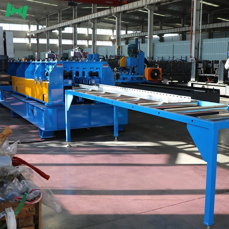
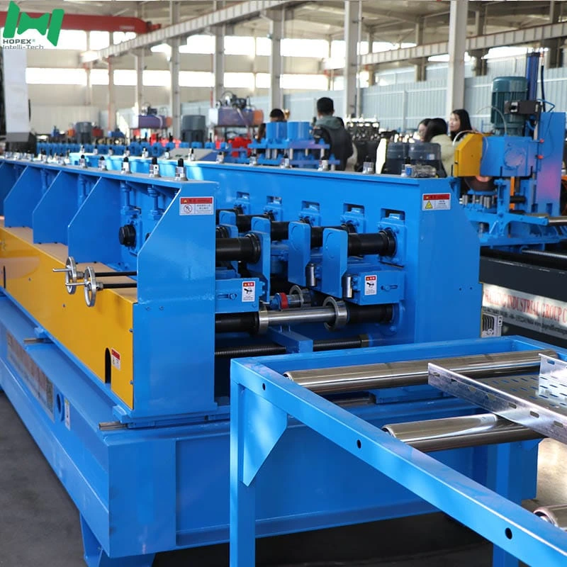
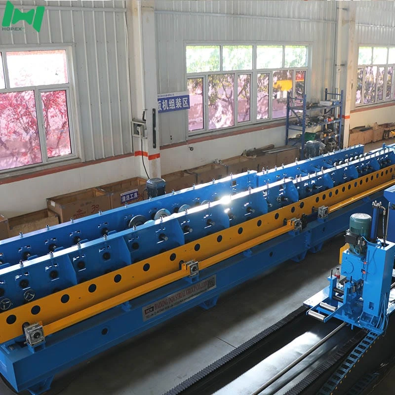
Cable tray forming line upgrade module for existing press-fed lines — replace the worn or under-spec forming mill without touching your decoiler, leveler, press or feeder. The 26-pass three-motor retrofit mill covers 50–600 mm base width × 50–100 mm height in 0.5–2.0 mm Q235 or galvanized strip, at 8–16 m/min, in a compact 10 × 1.5 × 1.6 m footprint drawing just 25 kW installed. Three distributed 5.5 kW motors replace single-motor chains, Modbus-ready INVT inverters integrate with existing PLCs, and commissioning takes 2–5 days — not 2–4 weeks like a full new line.
Planning a cable tray forming line upgrade for an existing press-fed production setup? This 50-600mm forming mill is the retrofit piece. It replaces a worn or under-spec forming main machine without touching the decoiler, press, leveler or feeder already on the floor. Moreover, it drops into a 10 × 1.5 × 1.6 m bay footprint, draws only 25 kW installed, and connects to an existing PLC line via standard Modbus — no electrical infrastructure upgrade required.
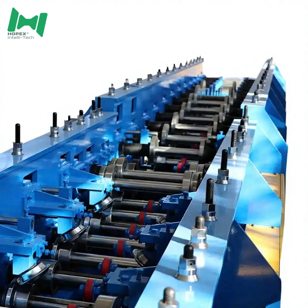
The mill runs 26 forming passes on a φ65 mm through-shaft driven by three distributed 5.5 kW main motors — a significant step up from the single-motor forming sections common on first-generation tray lines. Consequently, this cable tray forming line upgrade delivers distributed torque, lower chain stretch and a more consistent wall-angle across the full 50–600 mm width range. In short, it is the one component that fixes the output quality issues without rebuilding the whole line.
Three Scenarios Where a Forming Mill Upgrade Beats a New Line
Buying a full integrated tray line seems like the natural response to output quality problems. However, three specific scenarios make a targeted cable tray forming line upgrade the better decision:
Scenario 1 — The Press and Feeder Still Work Fine
If your 180T or 200T press is in good condition and the servo feeder holds pitch accurately, the front end is not your problem. Furthermore, worn or single-motor forming mills produce wall-angle drift and tolerance creep regardless of how good the front end is. Consequently, replacing only the forming mill fixes the actual failure point — not the functioning components around it.
Scenario 2 — You Need More Width Range Without Adding a Line
A first-generation single-motor mill typically runs reliably up to 400 mm base width. However, above 400 mm the forming load exceeds single-motor capacity without chain stretch or speed compromise. Therefore, a three-motor retrofit mill extends your width capability to 600 mm on the same floor area and the same front-end press — adding a SKU without adding a line.
Scenario 3 — Downtime Budget Is Limited
Installing a full new integrated line means decommissioning the existing one for weeks: new electrical supply, new foundation, new leveler commissioning. In contrast, a cable tray forming line upgrade — dropping a retrofit mill beside the existing press — requires only a short mechanical coupling and PLC handshake. As a result, the existing line stays productive while the new mill is installed and commissioned in parallel.
Cable Tray Forming Line Upgrade Mill at a Glance
What a Three-Motor Mill Buys Over a Single-Motor Retrofit
Most first-generation forming mills on the market and in existing factories use a single drive motor — often 7.5 kW or 11 kW — at one end of the mill, distributing torque through a long chain across all passes. However, this architecture has three well-documented failure modes over time:
- Chain stretch. A long chain under full forming load stretches unevenly, producing micro-speed variation pass-to-pass. Consequently, wall angle drifts as the chain wears, even with correct roller geometry.
- Start-up stall at full width. A single motor must overcome full breakaway torque at 600 mm base width. Additionally, this produces voltage dip events on shared factory supplies and accelerates motor thermal cycling.
- Single-point failure. One motor means one failure stops the mill. Furthermore, diagnostics on a single-motor mill require isolating the entire drive section.
This cable tray forming line upgrade runs three 5.5 kW motors distributed across 26 passes. As a result:
- Chain runs are short — torque is delivered close to where the forming load is
- Breakaway torque at full width is shared across three motors — no stall, no voltage dip
- One motor derated does not stop the mill — the other two maintain production at reduced width
Fitting the Retrofit Mill to an Existing Line
For this cable tray forming line upgrade to work with existing front-end equipment, three interfaces must align. The mill is designed for flexibility on all three:
1. Mechanical Strip Entry
The mill accepts 150–850 mm wide strip at any thickness from 0.5 to 2.0 mm. Furthermore, entry height and centreline are shimmed at commissioning to match whatever conveyor or feeder is upstream. Therefore, structural modifications to the existing line are typically not required.
2. Electrical Coupling
Power supply is 380 V / 50 Hz / 3-phase — standard for most Chinese and export industrial sites. Additionally, the INVT inverters on the three drive motors accept Modbus commands from an existing line PLC, so the mill can follow the upstream feeder’s speed reference without a separate control integration project.
3. Speed Matching
Line speed is adjustable from 8 to 16 m/min via the inverter. Consequently, the retrofit mill matches whatever pace the existing press or servo feeder runs — no throughput compromise from the speed mismatch that would occur with a fixed-speed motor retrofit.
Downtime Calculation — Retrofit Mill vs New Integrated Line
Downtime is the hidden factor in the upgrade-vs-replace decision. Notably, a retrofit mill and a full integrated line have very different commissioning footprints:
Furthermore, because the existing press and feeder remain live during retrofit mill installation, you can continue producing on the old mill right up to the changeover day. As a result, the retrofit path reduces lost production to days, not weeks.
The 26-Pass Width Range — What Each Zone Does
The 26-pass mill breaks into three functional zones. Understanding the zone split helps when aligning the retrofit mill to an existing line’s output quality targets:
Entry Zone — Passes 1–8
Pre-shapes the strip from flat to early wall angle. Consequently, spring-back from the initial bend is small and predictable — no sudden profile jump that would crack a worn roller edge.
Main Forming Zone — Passes 9–20
The twelve middle passes do the heavy forming work: raising wall angle toward 90°, forming the small-edge geometry, and beginning the base radius. Furthermore, this is where the second 5.5 kW motor delivers its torque — directly at the highest forming load zone.
Finish Zone — Passes 21–26
The last six passes finalise wall angle at 90° ± 2°, level the small edge, and remove spring-back with opposing-roller geometry. Additionally, these passes set the base flatness — the final determinant of tray-to-tray visual consistency.
Commissioning a Retrofit Mill — What to Check Before Sign-Off
A cable tray forming line upgrade commission is shorter than a full line — but the checks are just as important. Specifically, four items determine whether the retrofit mill will hold ±1.5 mm tolerance in production:
- Entry centreline alignment. The mill centreline must match the upstream conveyor centreline within ±1 mm. Furthermore, misalignment produces systematic wall-angle bias on one side.
- Speed synchronisation. The Modbus speed reference from the upstream PLC should be verified at 8, 12 and 16 m/min with a handheld tachometer. Additionally, confirm the inverter ramp time matches the feeder ramp time — a mismatch produces strip buckling at start-up.
- Roller contact verification. With a strip of the thinnest planned gauge (0.5 mm), run the mill at slow speed and check for roller bounce or chatter. Consequently, any loose bearing housing shows up at this stage, before production speed.
- Width preset accuracy. Call each standard width preset on the HMI and verify actual gap with a digital caliper. Furthermore, document the results as the baseline tolerance file for future maintenance reference.
Sourced Component Brands
Named parts. Therefore, spares for this cable tray forming line upgrade mill are locally sourceable worldwide.
Note: brands listed cover main equipment. Auxiliary parts may vary by production batch; substitutions are disclosed at order confirmation.
Where This Cable Tray Forming Line Upgrade Fits Best
Because it is a forming mill only — not a full line — this upgrade suits three specific buyer profiles:
Common Questions
What does “cable tray forming line upgrade” mean in practice?
It means replacing the forming main machine (the 26-pass roll-forming section) while keeping the decoiler, leveler, press and feeder from the existing line. Furthermore, the existing line continues producing on the old mill until the retrofit mill is commissioned and accepted. Consequently, production interruption is limited to the cutover day.
Can this mill run without a preceding press?
Only if you supply pre-punched, pre-sheared blanks from a separate upstream operation. Additionally, the mill has no punching or shearing station — it expects a flat blank at the entry. Therefore, it is designed to follow an existing press, not operate standalone.
What is the minimum existing press tonnage to feed this mill?
The mill does not prescribe upstream press tonnage — it accepts whatever blank the press produces. However, for 2.0 mm strip with dense hole patterns, a minimum of 160 T is recommended upstream to produce clean hole edges. As a result, a 180T or 200T existing press is the right pairing.
How long does the retrofit commissioning take?
Typically 2–5 days from mechanical coupling to first production piece within tolerance. Furthermore, if the existing PLC supports Modbus, electrical integration adds half a day. In contrast, a full new integrated line commissioning runs 2–4 weeks.
What is the total footprint?
10 m long × 1.5 m wide × 1.6 m high — small enough to install beside an existing line in the same bay, or in a 10-metre bay extension. Additionally, it draws only 25 kW installed, so most factory panels accommodate it without an infrastructure upgrade.
Bottom Line
If your factory already runs a decoiler, leveler, press and feeder — and the forming mill is the component producing wall-angle drift, tolerance creep or width limitations — this cable tray forming line upgrade is the targeted fix. It delivers a 26-pass three-motor distributed mill on a φ65 mm shaft with Cr12 rollers, in a 10 × 1.5 × 1.6 m footprint drawing just 25 kW installed, with Modbus integration to your existing PLC.
For retrofit engineering drawings, PLC integration documentation, or a walk-through of the commissioning checklist, contact our engineering team with your existing line details, target widths, steel grade and monthly output. Then we configure the roller tooling, drive synchronisation and control handshake to your upgrade plan.