
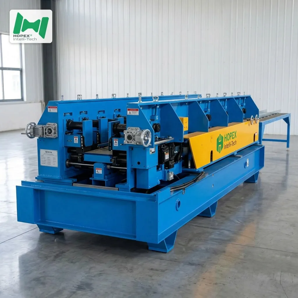
Automatic Cable Tray Machine 50-300mm
Fully automatic cable tray machine producing 50–300 mm × 50–100 mm trays across nine standard sizes at 15–20 m/min with one operator per shift. Runs 0.3–1.5 mm Q235 or galvanized strip up to 6000 mm long. Integrates 8-roller leveling, two-station hydraulic punching, hydraulic shearing and 22-pass forming with integrated side and bottom reinforcing ribs — all synchronised from one PLC, zero manual station hand-offs. Backed by an oversized 11 kW / 450 L three-bank hydraulic station to sustain two-station punch pressure at full line speed.
How many operators does your cable tray line need? If the answer is more than one per shift, the line is not fully automatic — it is semi-automatic with manual hand-offs between stations. This automatic cable tray machine closes that gap: one operator loads a coil, enters the size recipe on the HMI, and the line runs coil-to-finished-tray without touching the strip again. Moreover, it does this at 15–20 metres per minute across nine standard tray sizes from 50 × 50 mm to 300 × 100 mm, through a two-station hydraulic punch, a 22-pass forming mill, and a side and bottom reinforcing rib station — all in one continuous flow.
This automatic cable tray machine is engineered for 0.3–1.5 mm Q235 cold-rolled or galvanized strip, holds ±1 mm length and width tolerance, and produces workpieces up to 6000 mm long. Consequently, one operator on a single shift can produce the equivalent of what a two- or three-person semi-automatic line makes in the same hours. In short, it is the equipment specification for factories building tray output without building headcount.
What Full Automation Actually Means — Operator Count vs Machine Count
“Automatic” on a cable tray line can mean several things. Specifically, the distinction matters for staffing and output planning:
Furthermore, full automation means the servo feeder, two-station punch, hydraulic shear, conveyor and forming mill all run synchronised from one PLC — no hand-off between stations, no operator positioned between press and mill. As a result, one operator can supervise this line as a secondary task alongside a second machine in the same bay.
Automatic Cable Tray Machine at a Glance
How the Two-Station Punch Keeps Up With 20 m/min
Most cable tray lines with inline punching run at 5–12 m/min. However, this automatic cable tray machine reaches 15–20 m/min — and the reason comes down to one specific engineering choice: the two-station punch head.
A single-station punch works like this: stroke, reposition, stroke. Consequently, the strip must slow or stop between strokes while the die moves to the next hole position. Furthermore, at dense hole patterns the repositioning time becomes the speed bottleneck — not the mill.
A two-station punch head works differently. Specifically:
- Station A strokes — punches a set of holes at the current position
- While Station A repositions, Station B strokes — punches the next set at the next position
- The strip keeps moving at production speed throughout
As a result, the punch and the strip are never waiting for each other. Furthermore, because each station carries its own die, pattern variety within a tray run is achievable without changing the full die set. Additionally, the oversized 11 kW × 3 hydraulic station with 450 L tank maintains pressure across both stations simultaneously at full shift speed — no pressure drop, no timing inconsistency at 20 m/min.
Nine Standard Sizes, One Operator, One Shift
The automatic cable tray machine’s 50–300 mm width range and 50–100 mm height range yields nine standard sizes:
Furthermore, changing between any two sizes is a servo open/close preset on the HMI — no mechanical shim changes, no operator-assisted re-centering. Consequently, a one-person shift can run a mixed production schedule across the full nine-size range without slowing output between batches.
Reinforcing Ribs — Structural Stiffness From Thin Steel
At 0.3 mm strip thickness, a flat-section cable tray wall would be too flexible to span any meaningful installation distance. However, this automatic cable tray machine forms side reinforcing ribs and bottom reinforcing ribs integrated into the 22-pass mill sequence. As a result, the finished tray is structurally stiff even at the thinnest gauge:
- Side ribs stiffen the wall against inward collapse under cover weight and cable lateral pressure
- Bottom ribs stiffen the tray floor against downward deflection under cable fill
- Both sets form in-pass — not as a secondary operation — so the tray exits the mill fully formed in one continuous flow
Additionally, the rib geometry is optimised for the 50–300 mm width range, where the absolute deflection for a given span is more sensitive to rib count and position than on wider trays. Consequently, even a 300 mm × 100 mm tray at 0.5 mm gauge carries its rated cable load without mid-span sag.
6-Metre Workpiece — When and Why
Standard tray production targets 2000–3000 mm workpieces because most factory setups cannot handle longer pieces on the run-out. However, this automatic cable tray machine produces workpieces up to 6000 mm — and three project types specifically call for them:
- Warehouse and factory ceiling runs — long, clear-span bays with hangers every 3–4 m; 6-metre trays minimise joints per run
- Data-centre hot-aisle runs — server rows are typically 1.2 m wide and 10–12 metres long; 6-metre trays reduce splice points above live equipment
- Commercial open-plan office fits — suspended ceiling grids on 6-metre bays; one tray per bay eliminates mid-bay field splices
Furthermore, the 6-metre powered conveyor table between the punch station and the mill is what makes 6-metre workpieces practical — without it, the long blank would sag and buckle at the mill infeed. Consequently, the 6-metre workpiece capability is not a marketing claim but a direct result of the conveyor’s length matching the workpiece.
Full Automation Flow — Eight Stations, One PLC Loop
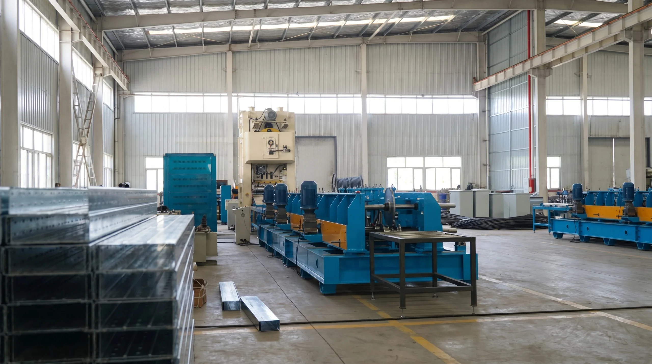
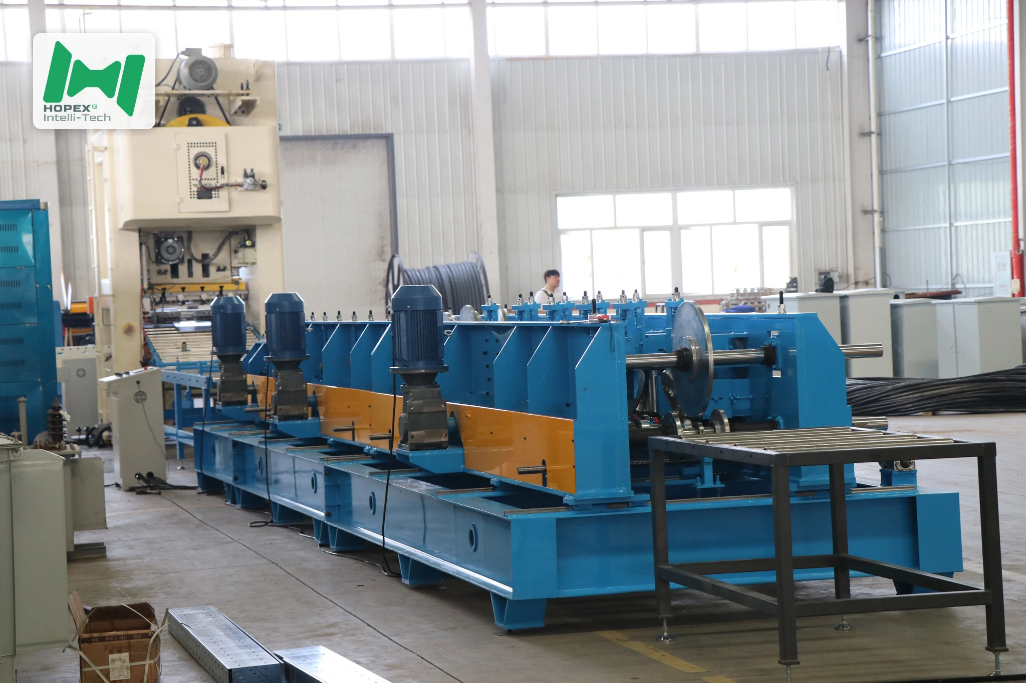
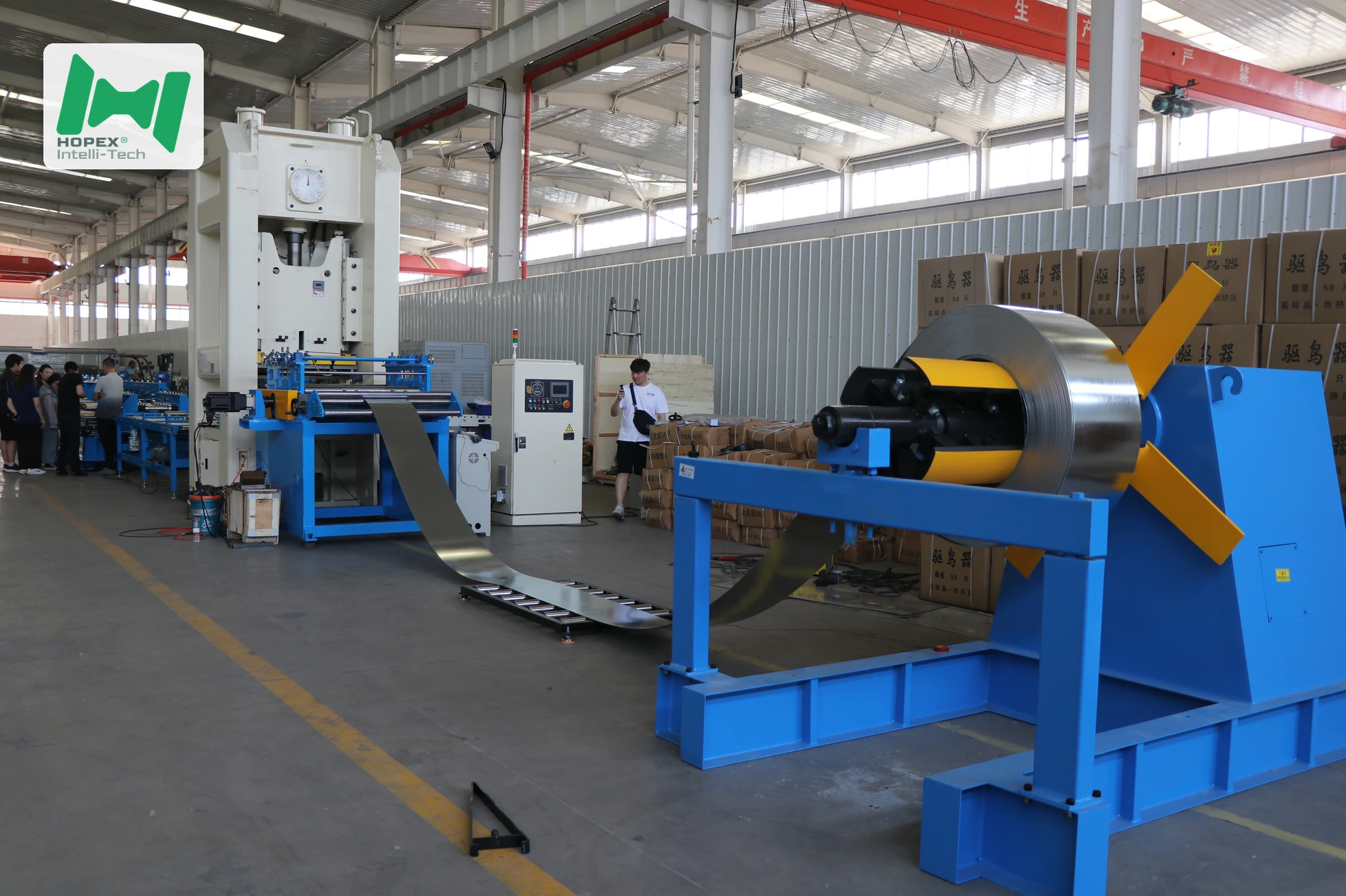
The automatic cable tray machine reads left to right in eight stations, all synchronised from one PLC:
Powered decoiler → 8-roller leveler with lift-linkage → Two-station punch + hydraulic shear → 6m conveyor → Small-edge forming → Main mill (22 passes + side and bottom ribs) → Run-out → 11 kW × 3 hydraulic station
1. Powered Decoiler (6-Ton)
Hydraulic expanding mandrel, electric drive. Inner diameter opens from φ460 to φ520 mm; outer accepts up to φ1500 mm. Thin 0.3 mm strip pays out under controlled motor tension — no manual brake adjustment, no strip breaks at high speed.
2. 8-Roller Leveler with Lift-Linkage
The 8-roller leveler with lift-linkage flattens the strip. At 0.3 mm, flatness is the most sensitive pre-punch variable — a single wave in the strip produces a skewed hole. Additionally, the lift mechanism re-threads the strip in seconds during coil changes, keeping downtime minimal.
3. Two-Station Punch + Hydraulic Shear
The two-station punch head alternates strokes while the strip moves continuously. Furthermore, the hydraulic shear shares the same frame — cutting blank length in the same PLC cycle that governs punch pitch. As a result, hole-to-cut registration holds at ±1 mm without a separate length-measurement loop.
4. Conveyor — 6-Metre Powered Table
The 6-metre powered roller table (electric open/close) carries the pre-punched blank at line speed. Because it matches the maximum workpiece length, the blank never hangs off the end — eliminating the sag-and-buckle failure mode at the mill infeed.
5. Small-Edge Forming
Six-pass small-edge station forms the 7–12 mm rim. Additionally, it carries a small-edge levelling roller to remove punch-induced lift before the blank enters the main mill.
6. Main Mill — 22 Passes + Integrated Ribs
Twenty-two forming passes on a φ50 mm shaft raise the walls, form the side reinforcing ribs and seat the bottom reinforcing ribs — all in one pass sequence. Main motor: 5.5 kW; open/close: 1.5 kW.
7. Run-Out Platform
A 3-metre passive idler run-out discharges finished trays without drive-roller surface marks.
8. Hydraulic Station — 11 kW × 3 / 450 L
An independent 11 kW station with three 5.5 kW valve banks at 220 V feeds both punch stations and the shear simultaneously. Consequently, pressure holds at 20 m/min without drop across full-shift running.
Sourced Component Brands
Named parts. Spares for this automatic cable tray machine are therefore locally sourceable worldwide.
Note: brands listed cover main equipment. Auxiliary parts may vary by production batch; substitutions are disclosed at order confirmation.
Where the Automatic Cable Tray Machine Earns Its Keep
Because it runs fully automatic at 15–20 m/min on one operator, this machine suits factories optimising tray output per person:
Common Questions
How automatic is “fully automatic” on this machine?
One operator: loads a coil, enters the size recipe on the HMI, and monitors output. Furthermore, the servo feeder synchronises with the two-station punch, the punch synchronises with the hydraulic shear, and the shear synchronises with the conveyor and mill — all from one PLC. Consequently, no manual step exists between coil entry and finished-tray discharge.
What is the thinnest strip this automatic cable tray machine can run?
0.3 mm — enabled by the 8-roller leveler with lift-linkage and the controlled tension payoff on the powered decoiler. Additionally, the two-station punch delivers smaller, cleaner punching forces at thin gauge than a full-tonnage single-station press, which reduces strip distortion at holes.
Why ±1 mm tolerance at 20 m/min?
The hydraulic shear shares its PLC cycle with the servo punch feeder — so cut position is triggered at the exact die-stroke position, not at a speed-approximated position. Furthermore, the ±1 mm tolerance holds across the full thickness range from 0.3 to 1.5 mm.
What reinforcing ribs does it form?
Side ribs on both walls and bottom ribs on the tray floor, formed in-pass during the 22-pass mill sequence. Consequently, rib formation does not require a secondary pass or a separate machine.
How long a tray can it make?
6000 mm (6 metres) — matched by the 6-metre powered conveyor between punch and mill. Additionally, 6-metre trays are standard for warehouse ceiling runs and data-centre server-row routing.
What is the total footprint and power draw?
35 m long × 1.8 m wide × 2.2 m high, drawing approximately 35 kW installed on 380 V / 50 Hz / 3-phase. The hydraulic station adds 11 kW.
Bottom Line
If your factory is building tray output per shift without building headcount, this automatic cable tray machine is the line to install. One operator loads a coil and the line runs at 15–20 m/min across nine standard sizes from 50 × 50 mm to 300 × 100 mm, punching two-station hydraulic holes, forming side and bottom reinforcing ribs, and cutting workpieces up to 6000 mm — all from 0.3 to 1.5 mm strip, at ±1 mm tolerance.
For HMI recipe documentation, two-station punch die layouts, or a walk-through of the full PLC synchronisation loop, contact our engineering team with your target sizes, hole pattern, steel grade and monthly output. Then we configure the punch stations, small-edge rollers and mill to your automatic production plan.