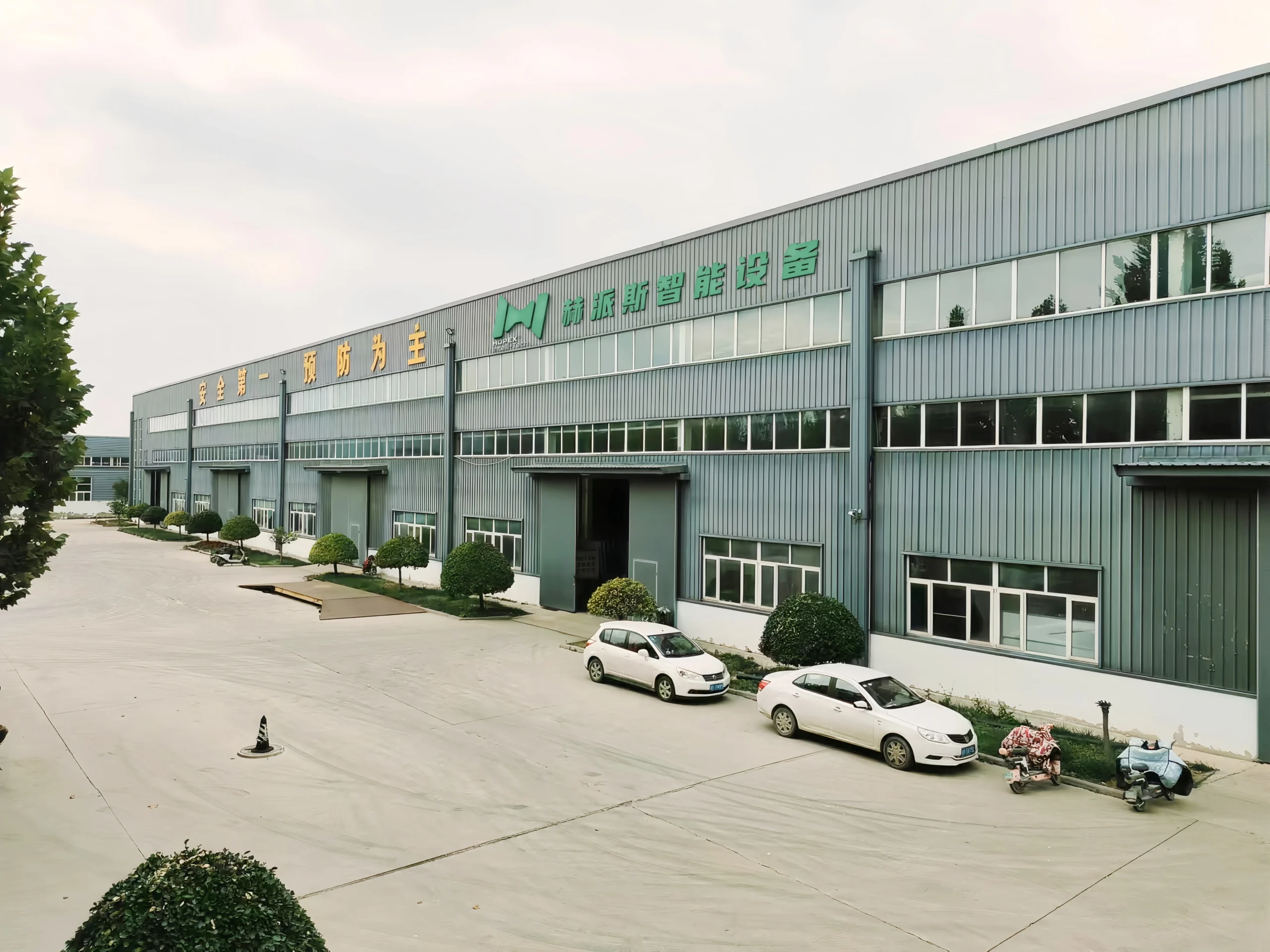
Factory layout planning is the absolute backbone of efficiency, safety, and profitability for any cable tray manufacturing plant. Cable tray production involves heavy-duty, multi-step processes—from coil decoiling and CNC punching to roll forming, welding, and surface treatments like Hot-Dip Galvanizing (HDG) or powder coating. A poorly designed floor plan leads to excessive material handling, bottleneck-induced delays, and increased safety hazards.
To help you eliminate waste and maximize throughput, this guide breaks down the essential strategies for designing a high-efficiency cable tray manufacturing line layout.
1. Analyzing the Cable Tray Production Flow
Before sketching any floor plan, it is critical to map out the exact sequence of operations. A standard, high-volume cable tray manufacturing process follows this sequence:
Raw Material Storage: Heavy steel coils or pre-cut sheets must be stored near the entrance, accessible by heavy-duty cranes or forklifts.
Decoiling & Leveling: The steel coil is unwound and flattened to prepare for continuous fabrication.
CNC Punching & Shearing: Holes for ventilation and coupling are punched, and sheets are cut to specific lengths.
Roll Forming / Bending: The flattened steel passes through roll forming mills to take the shape of ladder, tray, or channel profiles.
Welding & Assembly: For ladder-type cable trays, rungs are welded to the side rails using automated or manual welding stations.
Surface Treatment: Trays undergo pickling, galvanizing (HDG), or powder coating to ensure long-term corrosion resistance.
Packaging & Dispatch: Finished products are inspected, bundled, and moved to the shipping zone.
2. Core Principles of Lean Factory Layout Design
To achieve an efficient cable tray manufacturing layout, your design must eliminate unnecessary movement and optimize the relationship between man, machine, and material.
Establish a Unidirectional Material Flow
Because cable trays are heavy and long (typically 3 to 6 meters), back-tracking or “retrograde” movement drastically inflates labor costs and fork-truck traffic. Two layout shapes work best:
The I-Shaped Layout (Straight Line): Ideal for long, narrow buildings. Raw materials enter at one end, and finished goods exit at the exact opposite end.
The U-Shaped Layout: Highly efficient for wider square plants. The entry and exit points are on the same side, allowing shared use of logistics docks and easier supervision of workers.
Build in Modular Flexibility
Market demands shift frequently between ladder trays, perforated trays, and wire mesh trays. Your punching and forming zones should be modular. This ensures that when switching from heavy gauge carbon steel to light gauge aluminum, the tooling and station adjustments can be done rapidly without disrupting neighboring lines.
Strategic Work-in-Progress (WIP) Buffers
CNC punching and roll forming operate at much higher speeds than welding and surface coating. Without designated WIP buffering zones, your high-speed machinery will be forced into costly downtime, or your welding stations will be overwhelmed. Calculating precise Takt time allows you to size these buffers perfectly, balancing the production pulse.
3. Optimizing the 3 Critical Plant Zones
A. The Heavy Machinery Foundation Zone
Decoilers, heavy presses, and roll forming lines generate massive weight and continuous vibration. During factory layout planning, these machines must be assigned to reinforced concrete foundations with vibration isolation pits. Overhead cranes with high lifting capacities must fully cover this zone for seamless coil loading.
B. The Isolated Surface Treatment Zone
Hot-Dip Galvanizing and acid pickling involve hazardous chemical fumes and high heat. This zone must be structurally or environmentally isolated from the rest of the plant. Dedicated exhaust systems and wastewater treatment facilities must be positioned away from precision CNC machinery to prevent chemical corrosion.
C. Wide Logistics Corridors
Standard logistics paths fail when handling 6-meter-long metal bundles. Main transport lanes must be at least 4 to 5 meters wide to allow heavy forklifts to turn safely. Implementing a First-In, First-Out (FIFO) racking system in the raw material and finished goods zones prevents material stagnation.
4. Why Partner with an Industry Expert?
An optimized manufacturing layout designed by a seasoned expert delivers immediate, measurable bottom-line results:
Reduces material handling costs by up to 30% by eliminating wasted movement.
Boosts floor space utilization by 25%, allowing you to fit more lines into the same footprint.
Shortens lead times by 20%, giving you a massive competitive edge in order fulfillment.
Transform Your Cable Tray Production Today
Leverage 28+ Years of Industrial Expertise for Your Plant Blueprint.
With over 28 years of hands-on experience in heavy industrial planning, metal fabrication, and lean factory layout design, we don’t just draw plans— we deliver engineered blueprints optimized for ultimate profitability. Whether you are building a new facility from scratch or retrofitting an existing workshop, we ensure your materials flow seamlessly from raw steel to finished product, avoiding the costly layout mistakes that general designers make.
Contact Us to request your custom layout consultation and comprehensive ROI evaluation!