
In modern industrial and commercial infrastructure, the efficient management of electrical power and data cables is paramount. A robust cable tray and fittings system serves as the backbone of this infrastructure, providing a safe, organized, and flexible pathway for wiring. Unlike traditional conduit systems, a cable tray system allows for easier maintenance, better heat dissipation, and the scalability required for future upgrades.
This guide explores the essential components, connection methods, and installation basics of a comprehensive cable tray and fittings system, drawing on industry standards such as NEMA VE 2 and technical engineering practices.
Understanding the Cable Tray and Fittings System
A cable tray and fittings system is more than just a series of metal ladders or baskets. it is a modular engineering solution designed to support insulated cables used for power distribution, control, and communication. The “system” aspect is critical: the straight sections provide the primary path, while the cable tray fittings allow the path to change direction, elevation, or width, ensuring a continuous and grounded support structure.
For electrical engineers and contractors, selecting the right system involves balancing load capacity, environmental durability (corrosion resistance), and ease of installation.
Essential Components of the System
The versatility of a cable tray system lies in its modularity. The following table summarizes the key fittings used to navigate complex architectural layouts.
Table: Key Cable Tray Fittings and Components
The Role of Precision Fittings
When designing a cable tray and fittings system, the choice of radius for bends is a critical technical consideration. A standard radius (e.g., 12, 24, or 36 inches) must be selected based on the minimum bending radius of the largest cables being installed.
- Horizontal Bends: These are the most common fittings. A precision-engineered horizontal bend ensures that the cable sheath is not stressed during installation.
- Vertical Bends: “Vertical Inside” bends transition from horizontal to upward, while “Vertical Outside” bends transition from horizontal to downward. Proper alignment here prevents cable “kinking.”
- Reducers: These are available in straight, left-hand, or right-hand configurations. They are vital for maintaining a clean aesthetic and efficient space utilization when the number of cables is reduced.
Material Selection for Enhanced Performance
Choosing the right material for your cable tray and fittings system is as important as the structural design itself. The environment in which the system is installed dictates the longevity and maintenance requirements.
1. Aluminum (6063-T6 Alloy)
Aluminum is favored for its high strength-to-weight ratio and natural corrosion resistance. It is non-magnetic, which reduces power loss in high-current applications by eliminating hysteresis. aluminum systems are significantly easier to handle during installation, reducing labor costs.
2. Steel (Pre-Galvanized, Hot-Dip Galvanized, Stainless)
- Pre-Galvanized Steel: Best for indoor commercial applications with controlled environments.
- Hot-Dip Galvanized (HDG): The industry standard for outdoor or industrial environments. The zinc coating provides sacrificial protection against rust.
- Stainless Steel (304 or 316): Essential for chemical plants, food processing, or marine environments where extreme corrosion resistance is required.
3. Fiberglass (FRP/GRP)
In highly corrosive environments where metal is not suitable, or where electrical non-conductivity is required, fiberglass cable trays provide a durable alternative.
Design Considerations for Load and Span
A critical step in specifying a cable tray and fittings system is determining the load class. NEMA defines load classes based on the weight the tray can support over a specific span (e.g., Class 12C supports 100 lbs/ft over a 12-foot span).
- Static Load: The weight of the cables themselves.
- Concentrated Load: A single point load, such as a worker stepping on the tray (which should be avoided) or heavy equipment mounting.
- Environmental Loads: Ice, snow, and wind loads must be factored in for outdoor installations.
When integrating cable tray fittings like horizontal bends or tees, engineers must remember that these fittings often have lower load-bearing capacities than straight sections. Additional supports must be placed as close to the fitting as possible to prevent deflection.
Connection and Installation Basics
The reliability of a cable tray and fittings system depends heavily on how the components are connected and supported. Following NEMA VE 2 guidelines ensures both safety and longevity.
1. Mechanical Connections via Splice Plates
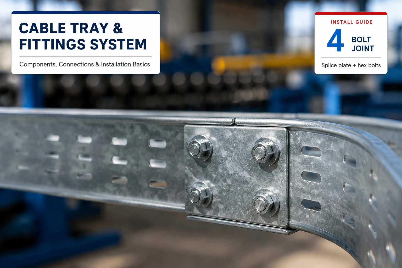
Splice plates are the primary means of connecting straight sections to each other and to fittings.
- Standard Splice: Used for rigid connections in most environments.
- Expansion Splice: Critical for long outdoor runs where thermal expansion and contraction occur. These plates allow for movement without compromising the structural integrity of the tray.
- Vertical Splice: Used to join sections at varying angles or to create field-fabricated offsets.
2. Support Spacing and Placement
Supports should be located so that splice joints are placed between the support and the quarter-point of the span. According to NEMA VE 2, supports should be placed within 2 feet (600 mm) of each side of a fitting to account for the additional weight and stress at turns.
Common support types include:
- Trapeze Hangers: Two threaded rods and a cross-member (strut). Ideal for multi-tier runs.
- Cantilever Arms: Wall-mounted brackets used when ceiling access is limited.
- Center-Hung Supports: Single-rod supports that allow for easier cable side-loading.
3. Thermal Expansion and Contraction
In outdoor installations, metal trays expand and contract with temperature shifts. As a rule of thumb from NEMA VE 2, a 100-foot run of aluminum tray can move by approximately 1.3 inches across a 100°F temperature swing; steel runs move less but are not exempt. Always consult the manufacturer’s expansion table for the exact spacing between expansion joints.
- Expansion Splice Plates: These allow the tray to move while maintaining alignment.
- Hold-Down Clamps vs. Expansion Guides: Use hold-down clamps at one point to anchor the tray, and expansion guides at other supphat all splice joints are tight.
- Use bonding jumpers across expansion joints or where the tray is not mechanically continuous.
- Verify that the tray material and cross-sectional area meet the requirements of NEC Article 392.
Installation Basics: The Process
- Layout and Alignment: Mark the path of the tray, ensuring clearance from high-heat sources and providing enough room for cable pulling (typically 12 inches of overhead clearance).
- Support Installation: Install trapeze hangers or wall brackets. Use a laser level to ensure the run is perfectly horizontal or follows the intended slope.
- Placing Straight Sections: Start from a fixed point (like a switchgear or wall penetration).
- Integrating Fittings: Secure horizontal bends, tees, and reducers as the path dictates. Always support fittings independently as per manufacturer recommendations.
- Securing Connections: Tighten all bolts on splice plates. For aluminum systems, ensure hardware is compatible to prevent galvanic corrosion.
Common Installation Mistakes to Avoid
Even experienced contractors can encounter issues if the nuances of a cable tray and fittings system are overlooked:
- Overloading: Exceeding the fill capacity or weight limit can lead to structural failure. Always calculate cable weight plus a safety factor.
- Neglecting Thermal Expansion: In outdoor or high-temperature environments, failing to use expansion splice plates can cause the tray to buckle or pull out supports.
- Poor Grounding: Treating the tray as a purely mechanical support and failing to ensure electrical continuity can create a significant safety hazard.
- Inadequate Support Near Fittings: Placing supports too far from a 90° bend can cause the fitting to sag under the weight of heavy power cables.
Conclusion
A well-designed cable tray and fittings system is essential for the long-term reliability of any industrial electrical installation. By understanding the specific roles of **horizonl-designed cable tray and fittings system is essential for t NEMA VE 2 installation standards, engineers can create a management system that is both safe and easy to maintain.
Whether you are navigating a complex intersection with crosses or adjusting capacity with reducers, the quality of the components and the precision of the installation will ultimately determine the system’s performance.
Frequently Asked Questions (FAQ)
Q1: Can I cut cable tray sections in the field? Yes, straight sections can be cut to length. However, you must use a square cut, de-burr the edges to protect cable jackets, and drill new holes for the splice plates as per the manufacturer’s template.
Q2: How do I choose between a 45° and 90° horizontal bend? This depends on the available space and the cable’s bending radius. A 45° bend is gentler and often preferred for high-voltage cables, while a 90° bend is more space-efficient for tight turns.
Q3: Are bonding jumpers always required at every joint? If the splice plates are UL-classified as grounding connectors and are tightened to the correct torque, separate bonding jumpers may not be required for standard joints. However, they are mandatory for expansion joints.
Q4: What is the benefit of using reducers instead of just overlapping trays? Reducers provide a continuous, smooth surface for cables, preventing sharp edges from damaging insulation. They also maintain the system’s UL/NEMA classification for structural integrity.