
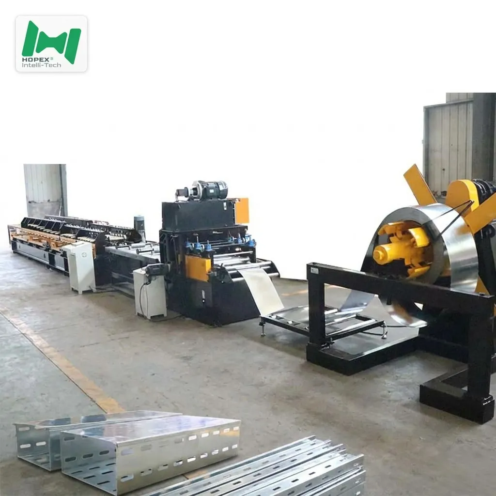
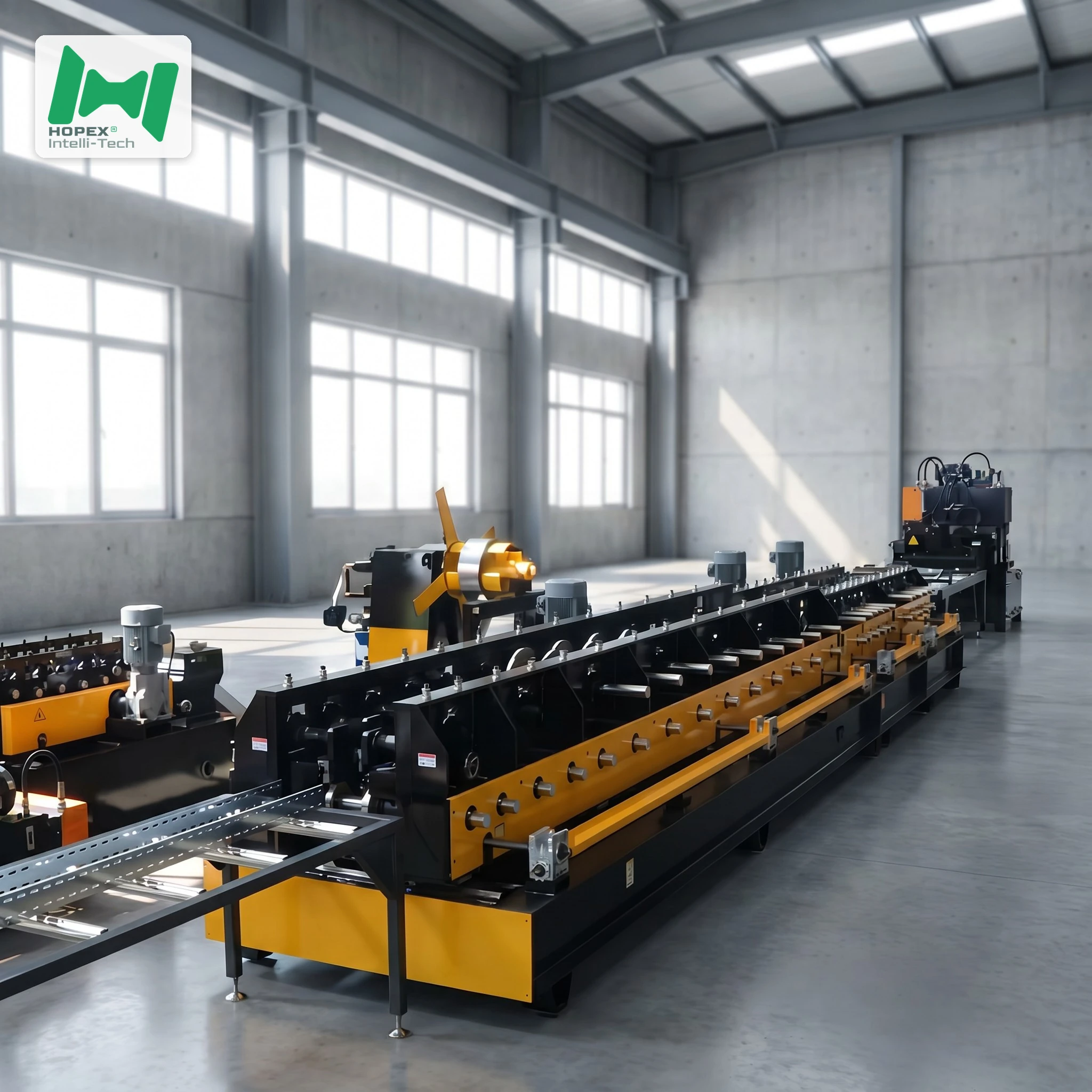
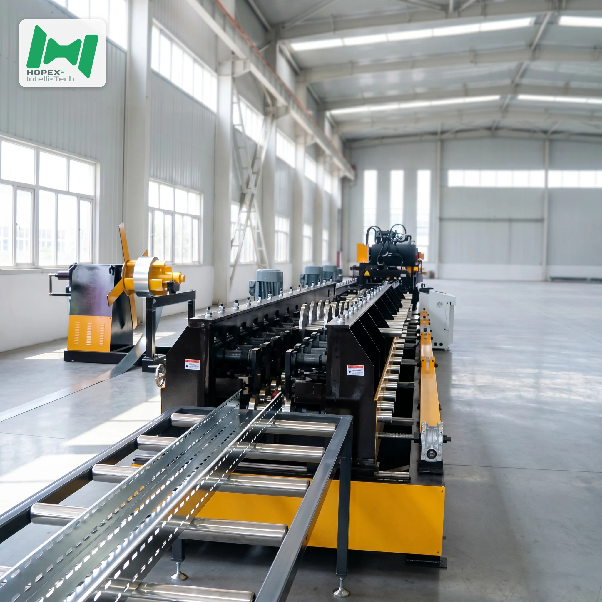
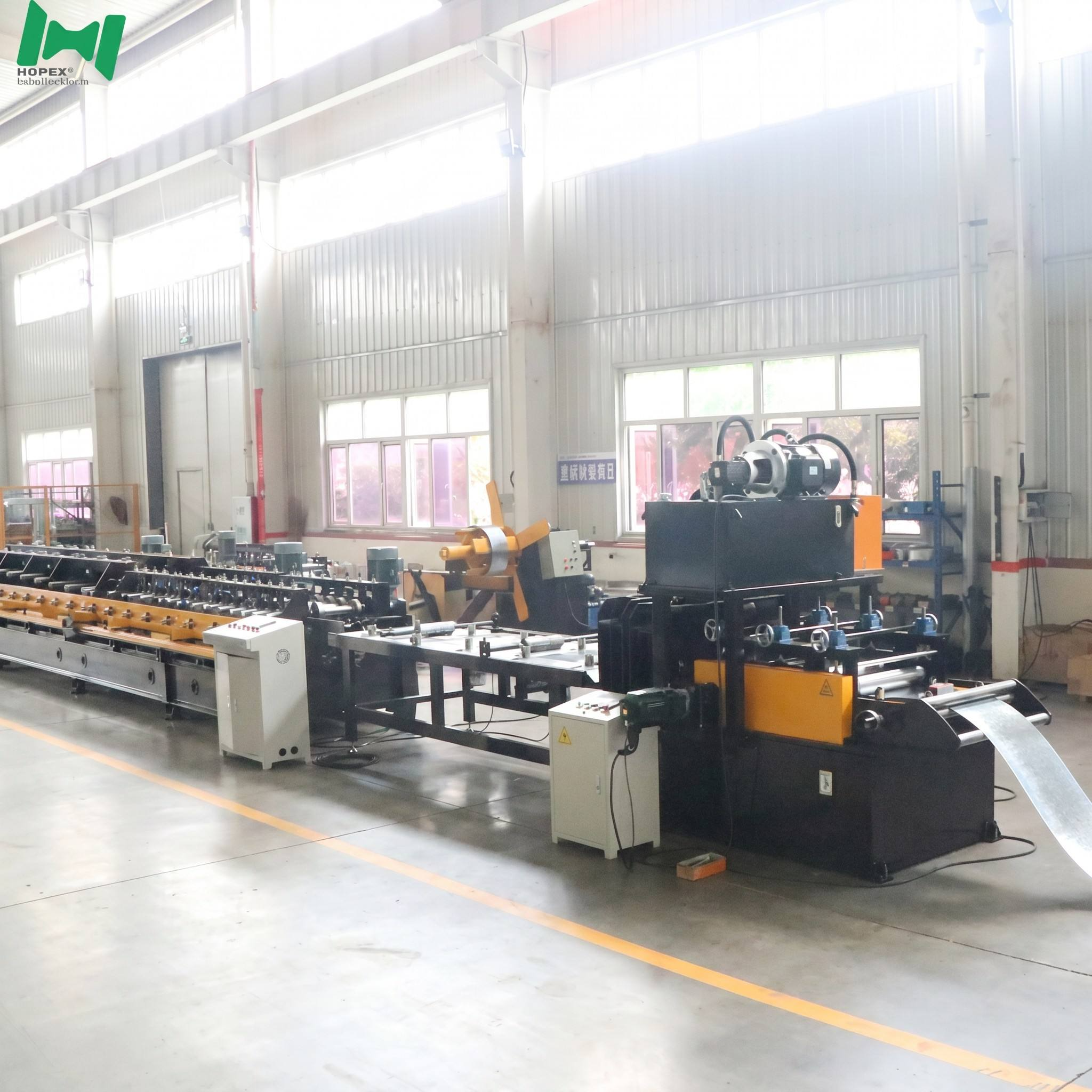
A cover either seats on the tray or it does not. There is no adjustment on site, no tolerance the installer can absorb. That pass-or-fail outcome is determined long before the cover reaches the job — it is decided station by station along the forming line.
This cable tray cover making machine produces covers from 101mm to 304mm wide, in steel at 0.6–0.8mm and aluminium at 0.8mm. What follows is the full path of a coil through the line, with the engineering reasoning at each stage.
Station 1 — Decoiling
The coil mounts on a hydraulically expanding mandrel.
Hydraulic expansion earns its place here. A mechanically clamped mandrel loosens progressively as the coil unwinds and its weight redistributes, and every variation in grip becomes a variation in feed tension. On 0.6mm cover stock, feed tension variation transfers straight into the forming section as inconsistent material presentation.
Three tons at 1600mm outer diameter accepts full mill coils rather than forcing purchase of pre-slit stock.
Station 2 — Guided Infeed
The guide shaft and guide roller set lateral position before the strip meets any forming tooling.
This is the cheapest correction point on the entire line. A millimetre of drift here becomes a permanently skewed cover profile twenty-two stations downstream — and by then the only fix is scrap.
Station 3 — Leveling
Coil stock arrives with memory: coil set from winding under tension, plus edge wave from slitting.
The 2-upper / 3-lower arrangement bends the strip alternately past its yield point in opposing directions, erasing that memory before forming begins.
For covers this station carries extra weight. A cover’s defining feature is a broad flat top surface, and flat surfaces show every defect. Residual coil set that would disappear inside a structural tray profile appears as visible waviness across a cover — the exact surface your client sees after installation.
Station 4 — Hydraulic Punching
Ventilation perforation is applied hydraulically.
The 400-litre tank is sized for thermal stability. Hydraulic oil heats during continuous operation; undersized tanks heat faster, viscosity falls, and punch force degrades as the shift progresses. Early production meets specification while late production does not — a failure mode that is difficult to diagnose because the machine appears to be running normally.
This station sets your line speed. Output runs 3–5 meters per minute, and punch density is the variable. Sparse patterns approach the upper figure; dense patterns settle toward the lower. Plan capacity against your actual perforation specification.
Station 5 — Main Roll Forming
Twenty-two stations, each contributing a small incremental bend.
Cover profiles look simple next to tray bodies — a flat top with return lips down each side. Simplicity is deceptive at 0.6mm. Thin material springs back unpredictably when deformed hard, and the return lip is precisely the feature that determines whether the cover grips the tray edge.
Distributing the total bend across 22 stations keeps deformation per station small, which keeps spring-back consistent and repeatable. That consistency is what makes cover number ten thousand fit the same as cover number one.
Chain drive delivers positive engagement across every station. No slip means no cumulative phase drift between stations — the profile stays dimensionally locked along the full stack.
Station 6 — Axial Straightening
Forming leaves residual twist and camber even when executed well, because material on one side of a profile is always worked slightly differently from the other.
Four rollers apply axial correction before cutting. On 7–8 meter steel covers this is not optional — over that span a small angular deviation compounds into visible bow, and a bowed cover will not sit flat along the tray run.
Station 7 — Rear-Insert Cutting
Cutting uses a rear-insert die with a scrap cut-off producing 5–6mm of scrap per cut.
The scrap is deliberate. A single-blade cut leaves a deformed, burred edge on the trailing piece. Removing a thin strip means the finished cover and the following cover both receive clean square ends — no secondary deburring, no rework before packing.
For covers this matters more than for tray bodies. A cover end is exposed and handled, and a burred edge is both a visible defect and a cut hazard for the installer.
Cut length is governed by the length encoder, holding accuracy across the full range: 4 meters for aluminium, 7–8 meters for steel.
Station 8 — Run-Out
Two 3-meter roller tables give six meters of supported run-out.
Thin-gauge covers sag under their own weight without support, and a 7–8 meter piece dropping onto an inadequate table deforms exactly where it just left the straightener. Heavy-wall square tube construction resists the frame flex that develops in lighter tables after years of impact loading.
The Tooling Behind It
Two hardness targets for two different failure modes.
Forming rollers fail by abrasive wear. Cr12 at HRC 58–62 holds profile geometry through long service — critical for covers, because a worn roller rounds off the return lip and a rounded lip no longer grips the tray edge.
Main shafts fail by fracture. At roller hardness a shaft would be brittle under chain-drive shock loading, so quenched and tempered 45 steel at HRC 28–32 trades peak hardness for toughness.
Both are machined to specification first, then heat treated — the correct sequence, since heat treatment moves dimensions.
Control Architecture
A XinJe PLC coordinates the sequence, INVT drivers govern motor output, and a XinJe Electric touch screen carries the interface.
The external jog controller deserves specific mention. Threading, die changes, and commissioning all require inching the line while watching the strip — not while standing at a cabinet twenty meters away. A handheld controller turns that into a one-person job.
Finished Cover Capability
As a dedicated Cable Tray Cover Roll Forming Machine, every station above is dimensioned for cover gauge rather than adapted from a tray body line.
Frequently Asked Questions
Which station limits throughput? Punching. Forming, straightening, and cutting keep pace with the drive; punch cycles per meter pull speed toward the lower end of the 3–5 meter per minute range.
Why does leveling matter more for covers than for tray bodies? Covers present a broad flat surface where any residual waviness is plainly visible. Tray body profiles hide minor surface variation inside structural bends.
Why is aluminium limited to 4 meters? Aluminium at 0.8mm is less stiff than steel at equivalent gauge. Shorter lengths stay rigid enough to handle and stack without permanent deformation.
What is the 5–6mm scrap for? It removes the deformed edge that shearing produces, so both the finished cover and the next piece exit with clean square ends and need no deburring.
How is cut accuracy maintained across materials? The length encoder reports actual strip travel, so cuts trigger on measured length rather than elapsed time — accuracy holds on 4-meter aluminium and 8-meter steel alike.
Plan Your Cover Line
Share your cover width range, material gauge, perforation pattern, and target monthly output. Our engineering team will confirm configuration and realistic throughput.