
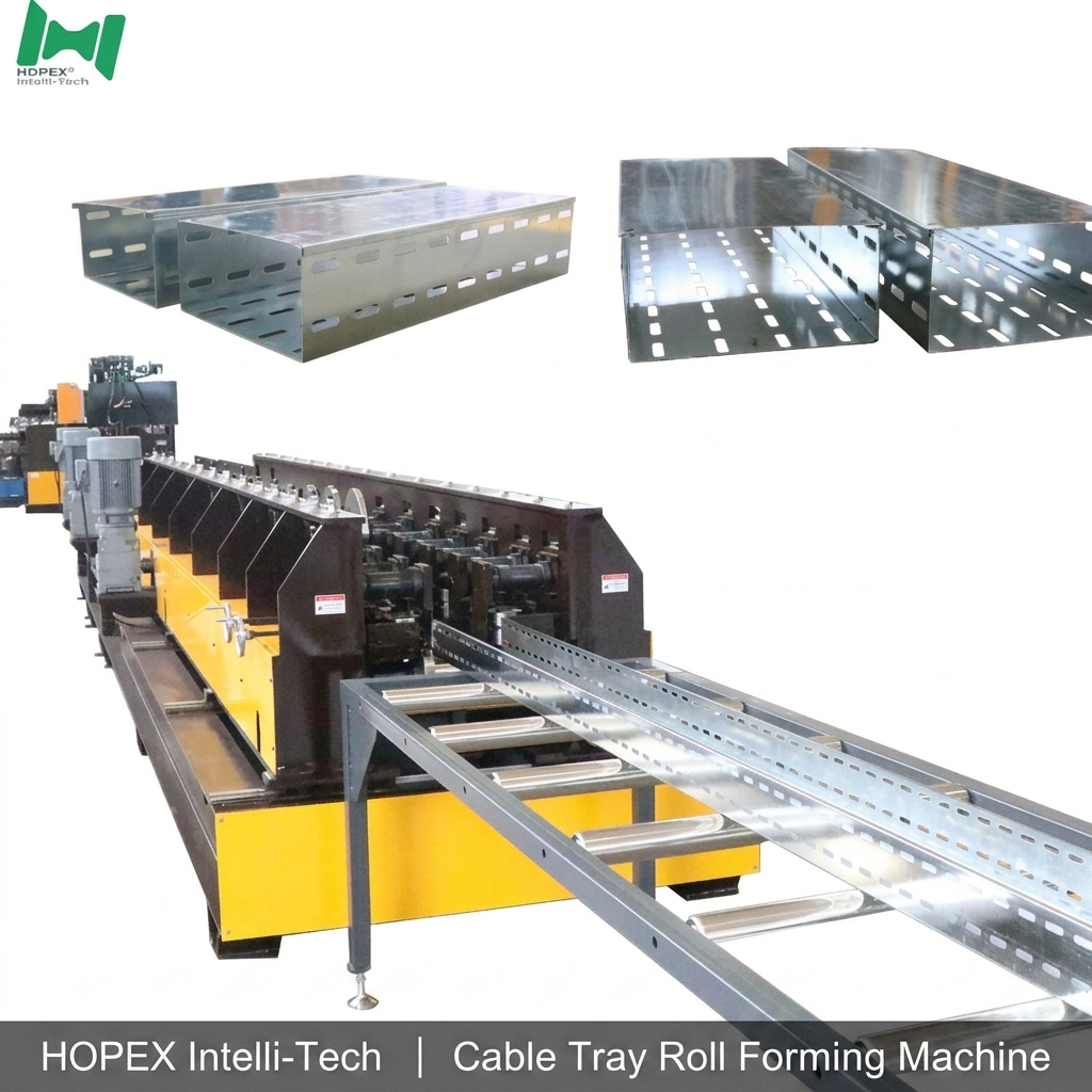
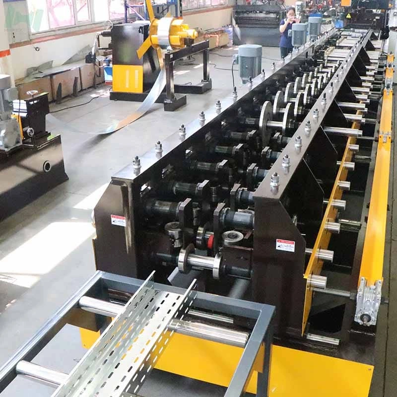
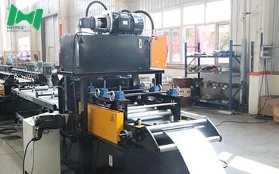
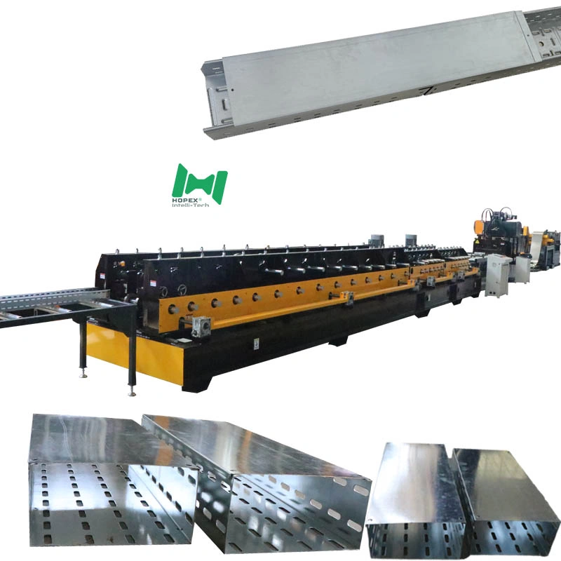
Cover lines are easy to compare badly. Two machines may list the same width range and the same output speed, yet one produces covers that seat cleanly for a decade while the other drifts out of fit tolerance within two years.
The difference sits in specifications most buyers skim: roller hardness, leveling roller count, transmission type, tank capacity. This guide walks the specification of a 101–304mm cable tray cover production line and explains what each figure actually tells you.
Question 1: Is the Line Dimensioned for Cover Gauge?
What to check: whether the thickness range is centred on cover stock or merely includes it.
This is the first filter, and it eliminates most general-purpose lines. Tray bodies carry load and run heavier gauge. Covers shed dust and water and run 0.6–0.8mm.
A line specified for 0.5–2.0mm technically covers both. In practice its tooling, drive, and leveling section are sized for the heavy end, and thin stock runs poorly through them. A dedicated Cable Tray Cover Roll Forming Machine is dimensioned around cover gauge from the start.
Ask suppliers what thickness their tooling was designed for, not what range it tolerates.
Question 2: Can It Hold a Flat Surface on Thin Stock?
What to check: leveling roller count, forming station count, and whether a dedicated straightener exists.
Covers are judged on their flat top surface — the one part of the assembly that stays visible after installation. Three specifications determine whether that surface comes out clean:
Five-roller leveling (2 upper / 3 lower) erases coil set before forming. Lines that skip leveling, or fit a token 3-roller set, pass coil memory into the forming section where it becomes permanent waviness.
Twenty-two forming stations keep deformation per station small. At 0.6mm, larger per-station bends produce cracked edges and inconsistent spring-back — and spring-back variation on the return lip is what makes covers fit inconsistently.
Dedicated 4-roller straightening removes residual twist and camber. Over a 7–8 meter cover, small angular deviation compounds into visible bow. A line without a straightener depends on the forming section being perfect, which it never quite is.
Question 3: How Long Will the Tooling Hold Fit Tolerance?
What to check: the hardness figure, and whether hardening happens after machining.
This is the specification most worth scrutinising, because on a cover line it determines how long your product keeps fitting.
Rollers at HRC 58–62 in Cr12. Rollers are consumable surfaces in continuous abrasive contact. Below roughly HRC 55 they wear into a rounded contour — and on covers, the first casualty is the return lip. A rounded lip no longer grips the tray edge, so covers that measure correctly still fail to seat.
Shafts at HRC 28–32 in 45 steel. Note the deliberately lower figure. A shaft at roller hardness would be brittle and prone to fracture under chain-drive shock loading. Quenched and tempered 45 steel trades peak hardness for necessary toughness.
Machined first, then hardened. Sequence matters, because heat treatment moves dimensions. Machining to specification and then hardening is the correct order — and it is what this specification states.
When comparing suppliers, ask for both the hardness value and the processing sequence. A supplier who cannot state both is not controlling the variable that governs product life.
Question 4: Is the Drive Built for Continuous Duty?
What to check: transmission type, and installed power relative to station count.
Chain drive gives positive engagement — every station turns in fixed mechanical relation to every other. Belt alternatives can slip under load, and slip means stations fall out of synchronisation, which shows up as inconsistent profile geometry along the run.
Two 4 kW motors distribute torque instead of loading one motor to its limit across 22 stations. Distributed drive lowers peak transmission stress and keeps roller speed uniform along the stack.
Question 5: Will Punch Force Stay Constant Through a Shift?
What to check: tank capacity, not just pump power.
Tank volume is routinely overlooked and directly governs consistency across a shift. Hydraulic oil heats in operation. Small tanks heat quickly, viscosity drops, punch force degrades — and the first hour of production meets specification while the last hour does not.
A 400-litre tank provides the thermal mass to hold oil temperature and viscosity steady through continuous running.
On the scrap cut: 5–6mm per cut is a design decision. Removing a thin strip leaves both the finished cover and the next piece with clean square ends, eliminating deburring. On covers this matters more than on tray bodies, since cover ends are exposed and handled.
Question 6: What Coil Can You Buy?
What to check: whether the decoiler takes standard mill coil, and how it clamps.
Three tons at 1600mm outer diameter accepts full mill coils. Lines limited to smaller coils force pre-slit stock, and you pay for that conversion step on every ton.
Hydraulic expansion maintains constant grip as the coil unwinds and weight redistributes. Mechanical clamping loosens progressively, and on 0.6mm stock that grip variation transfers into feed tension variation.
Question 7: Can One Operator Run It?
What to check: whether threading and commissioning need a second person.
Automation specifications describe production mode. The harder question is what happens during threading, die changes, and troubleshooting.
The external jog controller answers it. An operator inches the line forward or backward while standing at the strip, watching the material. Without one, threading needs a person at the cabinet and a person at the line — a permanent second-operator requirement hidden as a missing accessory.
The length encoder reports actual strip travel, so cuts trigger on measured length rather than elapsed time. Accuracy holds across 4-meter aluminium and 7–8 meter steel.
Question 8: What Output Should You Plan For?
What to check: the condition attached to the speed figure.
Speed is stated as a range because punch density decides the outcome. Sparse ventilation patterns approach 5 meters per minute; dense patterns settle toward 3. Plan against your actual perforation specification — a supplier stating one speed figure with no attached condition is describing a best case you may never reach.
Run-out capacity deserves a look too. Two 3-meter tables give six meters of support. Thin covers sag unsupported, and a 7–8 meter piece landing on an inadequate table deforms exactly where it just left the straightener.
Specification Summary
Frequently Asked Questions
Why do roller and shaft hardness differ so much? Different failure modes. Rollers fail by abrasive wear and need surface hardness. Shafts fail by fracture under shock load and need toughness. HRC 58–62 against HRC 28–32 reflects that split.
Is 22 forming stations excessive for a simple cover profile? No. Station count sets deformation per station. At 0.6–0.8mm, spreading the bend across 22 stations is what keeps spring-back on the return lip consistent — and lip consistency is what makes covers fit.
Should covers really run on a separate line from tray bodies? If cover volume justifies it, yes. Gauge mismatch degrades quality in both directions, and a heavy line producing light parts consumes capacity you need for structural work.
How much does perforation density reduce output? Enough to matter — it is why the range spans 3 to 5 meters per minute. Send your hole pattern and our engineering team will estimate realistic throughput.
What is included beyond the machine itself? One complete tool set, the 3-ton decoiler, and two 3-meter run-out tables as specified above.
Request a Specification Review
Send your cover width range, material gauge, perforation pattern, and target output. Our engineering team will confirm which configuration matches your requirement and what throughput to plan for.