
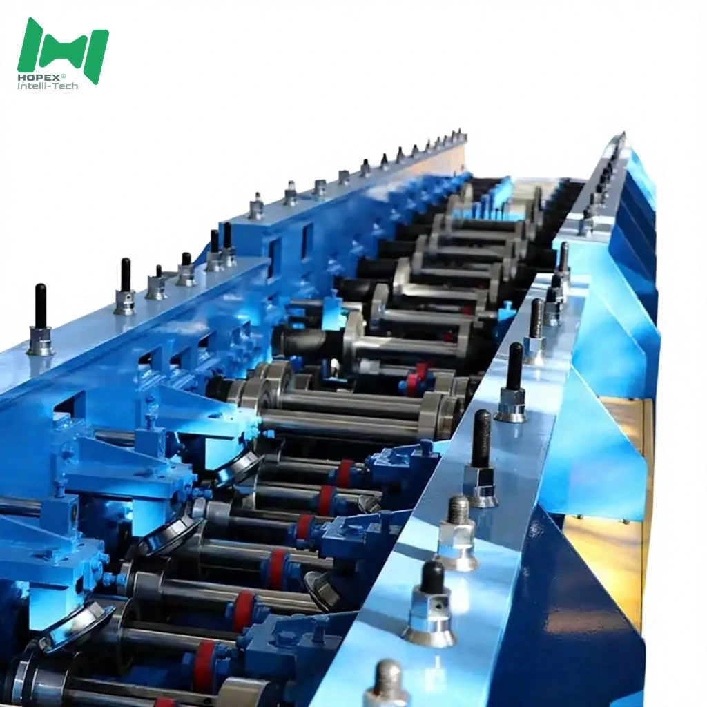
Cable Tray Manufacturing Machine 100-800mm
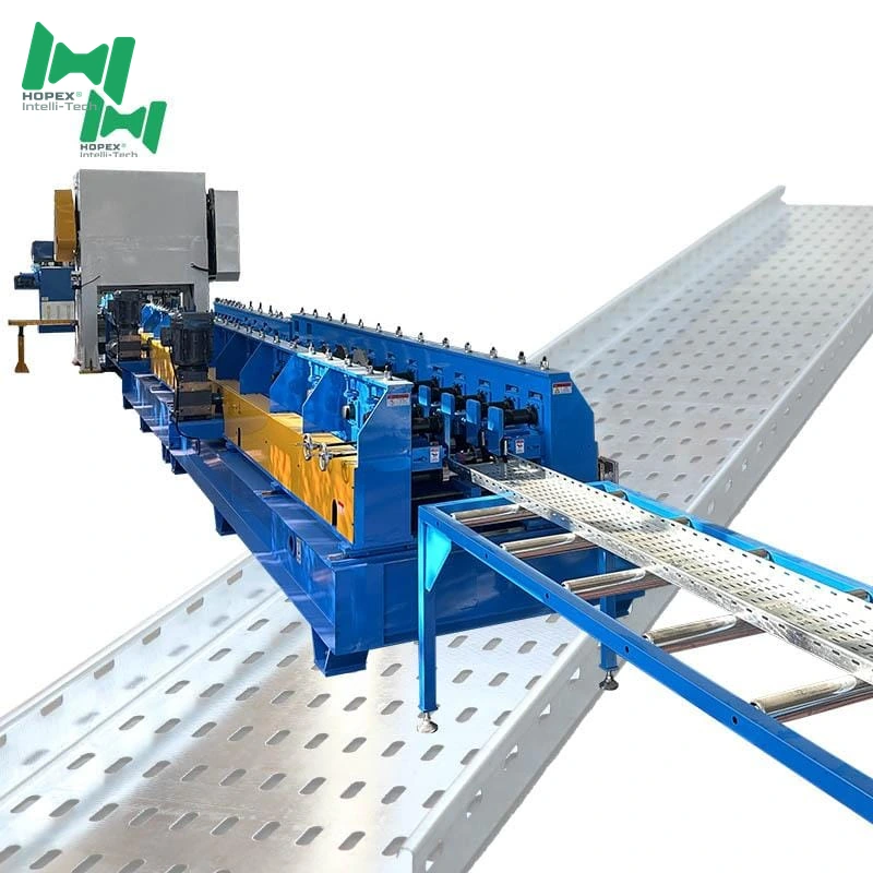
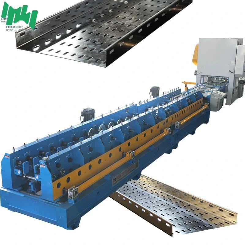
Heavy-gauge cable tray manufacturing machine for 100–800 mm base × 50–200 mm side trays up to 2.5 mm thick and 10 000 mm long — the widest, thickest and longest configuration in the series. Runs Q235 cold-rolled or galvanized coil through a 10-tonne decoiler, 12-roller leveler, two-station seven-shape punch, cover-plate forming module, and 26-pass rear mill on a φ80 mm shaft driven by twin 7.5 kW motors. Forms four side ribs plus two floor ribs for full structural stiffness. Built to CECS 31:2006 and GB cold-formed steel standards.
Need a cable tray manufacturing machine built for the heaviest end of the spec sheet? This 100-800mm line handles what smaller tray lines cannot: 2.5 mm plate thickness, 10-metre continuous workpieces, and 800 mm base widths with 200 mm side walls. Moreover, it runs an oversized 12-roller leveler, twin 7.5 kW × 2 main forming motors, and a 65 kW total installed power package — sized for utility, industrial, tunnel and infrastructure tray work, not commercial fit-outs.
This cable tray manufacturing machine ships as a gantry through-shaft line on a 42-metre footprint. Furthermore, it forms both side reinforcing ribs and bottom reinforcing ribs in the same pass, so the finished tray leaves the mill structurally stiff even at maximum width. In short, it is the equipment specification factories reach for when the project calls for the widest, thickest, longest cable trays in the catalogue.
Three Numbers That Define This Line
Most tray lines top out at 600 mm width, 100 mm height, 2.0 mm thickness, and a 6-metre workpiece. However, this cable tray manufacturing machine pushes every one of those ceilings meaningfully higher:
1. Up to 2.5 mm Plate Thickness
The mill is rated for 0.5 to 2.5 mm strip on Q235 cold-rolled or galvanized coil. As a result, buyers producing MV cable tray, tunnel tray or heavy-industrial tray can spec the actual gauge their engineering standards require — not the thinner substitute a lighter line would force.
2. Up to 10,000 mm Workpiece Length
The line’s 6-metre powered feed table × 2 units and cut-off geometry support finished workpieces up to 10 metres long. Consequently, one tray can span a full tunnel bay, a warehouse aisle or a bridge deck section without a splice — reducing installation joints, labour and future maintenance points.
3. Up to 800 mm Base × 200 mm Side
Base widths from 100 to 800 mm and side heights from 50 to 200 mm cover the full catalogue for trunk cable runs, MV distribution, and utility infrastructure. Furthermore, the small edge is formed at 8–15 mm for standard cover-fit tolerances.
Cable Tray Manufacturing Machine at a Glance
Standards This Machine Is Built To
The line is engineered against the standards its output must comply with. Notably:
Consequently, trays produced on this line meet the same dimensional and geometric standards specified in Chinese and export tender documents for utility and infrastructure projects.
Why the 12-Roller Leveler Matters at 2.5 mm
Leveling is the piece of the line most buyers overlook — until they run 2.0 mm or thicker coil and see waves on the finished tray. Specifically, thick strip carries internal stress that a short leveler cannot absorb; the strip springs back after each roller and re-develops waves before it reaches the punch.
This cable tray manufacturing machine carries a 12-roller leveler. Furthermore, twelve rollers means six reverse-bend cycles instead of three or four — enough to work-harden the strip past its yield point in both directions and eliminate residual stress. As a result, 2.5 mm strip enters the punch flat and stays flat through the mill.
Additionally, the leveler runs a lift-linkage mechanism, so operators can lift the top rollers to re-thread coil in seconds during changeover.
Reinforcing Rib Architecture
A wide tray without rib reinforcement sags under its own cable load. Therefore, this line forms structural ribs at three locations:
- Side ribs (walls) — 2 ribs on each wall (4 total) — stiffen the sides against inward collapse under cover weight
- Bottom ribs — 2 ribs in the tray floor — stiffen the base against downward deflection under cable weight
- Opposing-roller final forming — the last mill section uses opposing rollers to seat the rib geometry cleanly
Consequently, an 800 mm × 200 mm tray formed on this line carries rated cable weight across a full installation span without intermediate support.
Full Line Walk-Through
The line reads left to right in eight stations:
10-tonne decoiler → 12-roller leveling + shearing → Two-station punch (7-shape holes) → Cover-plate forming section → Main forming (rear) → 2 × 6-metre feed tables → 3-metre run-out → 2 × 7.5 kW hydraulic station
1. Decoiler — 10-Tonne Hydraulic
The coil sits on a hydraulic expanding mandrel with electric drive. Additionally, the mandrel is rated for a 10-tonne coil — enough for continuous 2.5 mm strip runs without frequent coil changes.
2. Leveling · Punching · Shearing — Combined Front End
The 12-roller leveler with lift-linkage flattens the strip. Furthermore, the front end integrates:
- Large-span seven-shape hole punching (large-pitch connection holes)
- Cut-off shearing in the same frame
- Tray-floor holes (optional module)
As a result, the strip goes in as coil and comes out as a pre-leveled, pre-punched, pre-sheared blank ready for forming.
3. Two-Station Punch Head — Seven-Shape Holes
The two-station punch head punches the seven-shape (“7-shape”) connection hole pattern — the standard connection geometry for steel cable tray joints. Additionally, an optional 0.5–1.5 mm marking punch stamps identification onto each blank.
4. Cover-Plate Forming Section
This module handles the small-edge geometry and initial wall raising. Specifically, it carries:
- Electric infeed for smooth blank entry
- 8-pass roll forming of the small edge
- Small-edge levelling to remove punch-induced lift
- Guiding for centreline control
- Scale-plate pressure adjustment for repeatable settings
- Spring-adjusted pressure for fine tuning
- Side reinforcing rib forming — first pass
Main motor: 7.5 kW. Open/close motor: 1.5 kW.
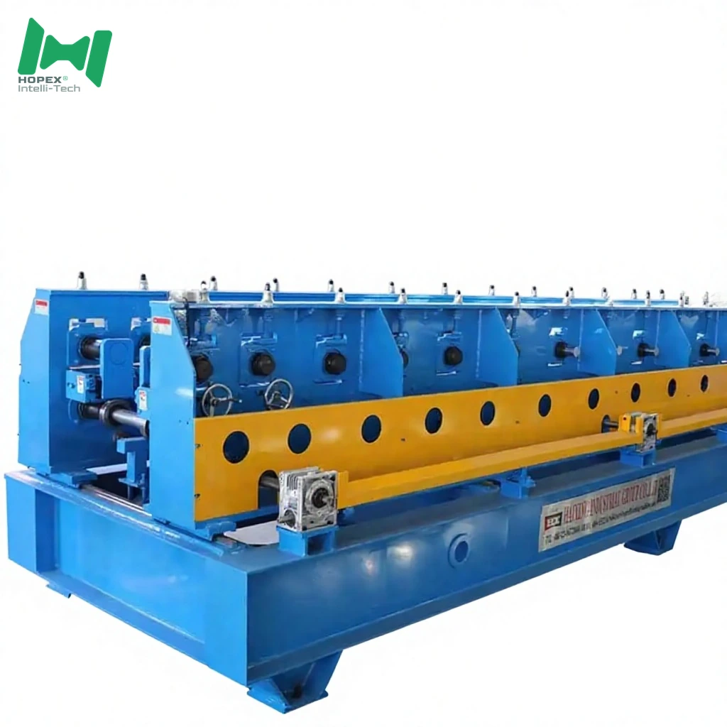
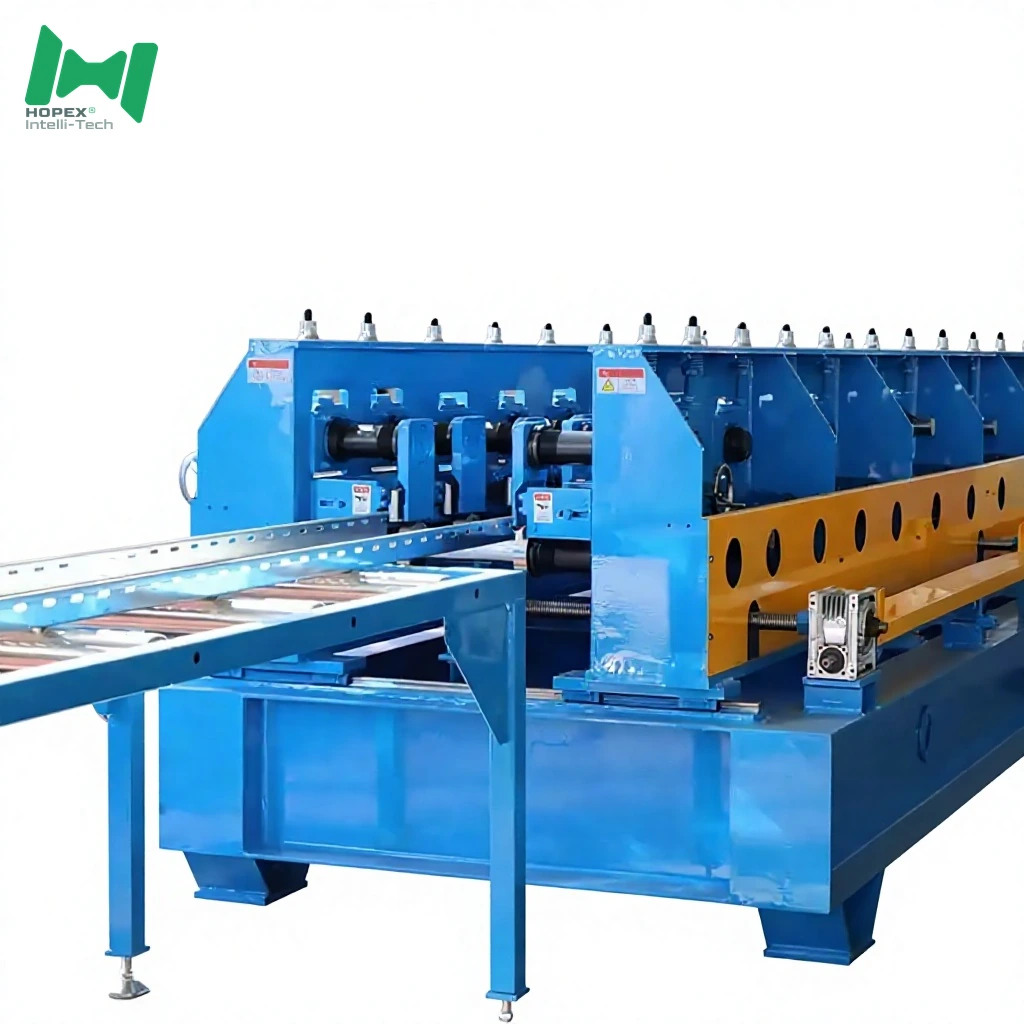
5. Main Forming Mill — Rear Section
The rear mill finishes wall geometry and locks in the profile. Notably, it forms:
- Side reinforcing ribs — 2 additional ribs per wall
- Bottom reinforcing ribs — 2 ribs in the floor
- Opposing-roller final forming — clean rib seating
Twin main motors: 7.5 kW × 2. Open/close: 1.5 kW.
6. Feed Tables — 2 × 6-Metre Powered
Two 6-metre heavy roller feed tables (1.5 kW × 2, electric open/close) carry long workpieces without sag. Consequently, the line supports up-to-10-metre finished trays without hand support.
7. Run-Out Platform
A 3-metre passive idler run-out carries finished trays off the mill for pick-up or crane-lift.
8. Hydraulic Station — 2 × 7.5 kW / 450 L
An independent twin 7.5 kW station with 450 L oil tank feeds the punch, shear and all servo actuators. Furthermore, three-station valve banks at 220 V, multiple solenoid valves, and active cooling hold pressure across full-shift running.
Where the 100-800mm Cable Tray Manufacturing Machine Fits Best
Because it handles the widest widths, deepest walls, thickest gauge, and longest workpieces in the series, this line suits fabricators serving the heaviest project categories:
Cable Tray Manufacturing Machine Component Brands
Named parts. Therefore, spares for this cable tray manufacturing machine are locally sourceable worldwide.
Note: brands listed cover main equipment. Auxiliary parts may vary by production batch; substitutions are disclosed at order confirmation.
How This Cable Tray Manufacturing Machine Compares
If you are sizing between this 100-800mm line and a lighter tray line, here is the practical split:
Common Questions
Does this cable tray manufacturing machine really run 2.5 mm?
Yes. Q235 cold-rolled or galvanized strip from 0.5 to 2.5 mm is on the approved feedstock list. Furthermore, the 12-roller leveler, φ80 mm shaft and twin 7.5 kW main motors are the components that make 2.5 mm production sustainable at line speed.
What is the longest tray this line can produce?
10,000 mm (10 metres). Consequently, one tray can span a full tunnel bay, a warehouse aisle or a bridge deck section without a splice — which cuts install time and eliminates joint maintenance later.
What kind of hole pattern does it punch?
The line punches the standard seven-shape connection hole at large pitch on both walls, plus optional tray-floor holes for ventilation. Additionally, an optional 0.5–1.5 mm marking punch stamps identification onto each blank.
How many reinforcing ribs, exactly?
Six ribs per tray: two on each side wall (four total) and two in the tray floor. As a result, an 800 × 200 mm tray formed on this line stays dimensionally stable under rated cable load.
Why twin 7.5 kW main motors on the rear section?
Wide, thick, high-side-wall profiles need torque, not just speed. Therefore, the rear forming mill runs twin 7.5 kW motors to drive the opposing-roller final section without stalling on 2.5 mm 800 mm-wide strip.
What is the line speed at maximum gauge?
8–16 m/min with inline hole punching. Additionally, at 2.5 mm × 800 mm × 200 mm, speed runs toward the 8 m/min end; lighter profiles run near 16 m/min. Hole pattern density also governs cycle time.
What is the total footprint and power draw?
42 m long × 2.5 m wide × 1.5 m high, drawing approximately 65 kW installed on 380 V / 50 Hz / 3-phase. Additionally, the dedicated hydraulic station is 2 × 7.5 kW with a 450 L oil tank.
Which international standards is this line built against?
Six standards: CECS 31:2006, GB/T 6725-2002, GB/T 6728-200, GB 6723-86, GB/709-88, and GB/708-88 — covering cable tray design, cold-formed steel technical conditions, and hot- / cold-rolled plate dimensional tolerances.
Bottom Line
If your production plan calls for heavy-gauge, wide-body, long-piece cable trays for utility, tunnel, MV or infrastructure work, this 100-800mm cable tray manufacturing machine is the equipment for it. It combines a 10-tonne decoiler, a 12-roller leveler with lift-linkage, a two-station seven-shape punch with integrated shear, a dedicated cover-plate forming module, a 26-pass rear mill on a φ80 mm shaft with twin 7.5 kW main motors, and dual 6-metre feed tables — all inside a 42 × 2.5 × 1.5 m footprint drawing roughly 65 kW, backed by a twin 7.5 kW hydraulic station with a 450 L oil tank.
For engineering drawings, custom hole-pattern intake, or a walk-through of the 12-roller leveler on 2.5 mm coil, contact our project team with your target dimensions, hole layout, steel grade and monthly output. Then we configure the die, rollers and mill to your production plan. . Then we configure the die, rollers and mill to your production plan.