
Cable Tray Production Line 50-600mm
Efficient cable tray production line for six standard sizes from 50 × 50 mm to 600 × 100 mm in 0.7–2.0 mm Q235B cold-rolled, hot-rolled or galvanized steel. Draws just 40 kW installed with a single 5.5 kW main motor — fits 63A factory distribution without a transformer upgrade. Holds ±1 mm tolerance through an 8-roller servo leveler and servo pitch feeder, with HRC58-62 Cr12 rollers on a φ65 mm shaft across 25 forming passes. Includes a 4-metre heavy conveyor and 5.5 kW / 300 L hydraulic station on a compact 40 × 1.5 × 1.6 m footprint.
Not every factory needs a 60-kW, triple-motor cable tray line. Many need a cable tray production line that covers the full standard size range — 50 × 50 mm to 600 × 100 mm — at a sensible installed power, with one main motor they can actually maintain. This 50-600mm line does exactly that. Moreover, it puts six finished sizes, a 25-pass HRC58-62 mill, an 8-roller leveler and a 180-tonne press into a single 40 kW package on a 40-metre footprint.
The line handles 0.7–2.0 mm Q235B cold-rolled, hot-rolled or galvanized coil at 8–12 m/min, holds ±1 mm on both length and width, and finishes the job with a single 5.5 kW main motor — not a triple-drive system. Consequently, maintenance is simpler, running current is lower, and the line fits into grid supplies where 60-kW or 65-kW lines would require an upgraded transformer. In short, this is the cable tray production line specification that factories choose when efficiency matters as much as throughput.
The 40 kW Argument — Why Lower Installed Power Is Better
Installed power on a roll-forming line is not a proxy for quality. Furthermore, it directly determines three operating factors that compound every shift:
1. Electricity Draw Per Tonne of Output
A cable tray production line drawing 40 kW installed versus one drawing 60 kW uses one-third less electricity per shift at equivalent throughput. Additionally, because most industrial electricity tariffs in Southeast Asia, the Middle East and South America bill on both consumption and peak demand, a lower-power line reduces two line items on every monthly invoice.
2. Transformer and Cable Infrastructure
Factories adding a second tray line often face a binary choice: upgrade the electrical infrastructure or choose a line that fits the existing supply. Therefore, a 40 kW line — versus a 60 kW line — fits more existing 63-ampere factory distribution boards without a transformer upgrade. As a result, commissioning is faster and the electrical side of installation is simpler.
3. Maintenance Simplicity
A single 5.5 kW main motor means one motor to service, one inverter to calibrate, and one set of drive sprockets to inspect. Furthermore, triple-motor lines require synchronisation tuning across three drives — a specialised task that single-motor lines simply do not have.
Cable Tray Production Line at a Glance
Six Sizes, One-Motor Drive — The Arithmetic of Efficiency
Six standard tray sizes off a single 5.5 kW main drive sounds like a trade-off. However, the arithmetic is straightforward: the 25-pass mill on a φ65 mm shaft spreads forming load progressively across stations, so peak torque at any single station is far lower than a short-pass mill trying to do the same job in fewer bends. Consequently, one 5.5 kW motor is sufficient.
Furthermore, the 1.5 kW automatic open/close motor handles width preset changes from the HMI. Therefore, moving between all six sizes is a stored recipe call — no mechanical strip-down between batches.
Four-Metre Conveyor — Why the Extra Metre Matters
Most cable tray production lines ship with a 3-metre conveyor between the press and the mill. However, this line comes with a 4-metre heavy-duty powered roller table (1.5 kW main, 0.75 kW electric open/close). Furthermore, the extra metre matters in three specific ways:
- Buffer decoupling. The longer conveyor lets the press and mill run at slightly different cycle rates without stalling each other. As a result, press efficiency and mill efficiency are optimised independently.
- Longer blank handling. At 3000 mm workpiece length, a 3-metre conveyor barely fits the blank. Additionally, a 4-metre table gives the blank room to settle before the mill pulls it in.
- Operator safety clearance. A longer buffer zone between press and mill entry gives an operator room to check blank quality without reaching into either machine’s working area.
Consequently, the 4-metre conveyor is not a luxury — it is what enables reliable, consistent 3000 mm tray production on this line.
HRC58-62 Rollers — Why Hardness Specification Matters
Most roll-forming catalogues list “Cr12 rollers” without specifying hardness. However, Cr12 tool steel can be delivered anywhere from HRC45 to HRC65 depending on heat treatment. Furthermore, rollers at HRC45-50 deform progressively under 2.0 mm forming load — producing consistent trays for the first few thousand pieces, then drifting out of tolerance as roller profile wears.
This cable tray production line specifies rollers at HRC58-62 — confirmed by delivery documentation. Consequently:
- Profile accuracy holds across millions of forming cycles, not thousands
- 2.0 mm hot-rolled coil does not deform the rollers over a full production run
- Changeover between roller sets happens on a planned maintenance schedule, not because tolerance has drifted
Additionally, the φ65 mm 45# steel through-shaft is dimensioned to match the roller spec — no deflection under the load HRC58-62 rollers can sustain.
What ±1 mm Tolerance Means in Practice
This cable tray production line holds ±1 mm on both length and width — tighter than the ±1.5 mm typical of press-punched lines at this gauge band. Furthermore, ±1 mm matters at the installation stage for two reasons:
- Fitting alignment. Trays joining end-to-end with ±1 mm tolerance align within a 2 mm joint gap. Additionally, trays at ±1.5 mm can produce a 3 mm gap — visible on exposed-ceiling installations and problematic for pre-drilled cover fitment.
- Tender compliance. Some EPC and data-centre specifications explicitly call out ±1 mm on cable tray geometry. Consequently, a line that only holds ±1.5 mm fails incoming inspection regardless of visual quality.
The ±1 mm tolerance on this line is a result of the 8-roller servo leveler (which eliminates coil-set waviness before the press) and the servo pitch feeder (which holds blank length to die-stroke position, not approximated by speed).
Full Line Walk-Through
The line reads left to right in six stations:
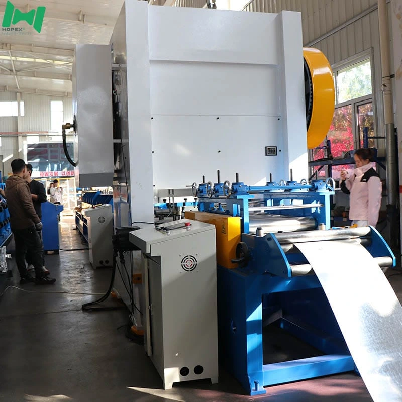
6-tonne decoiler → 8-roller leveler + servo feeder → 180T press (punch + shear) → 4m heavy conveyor → 25-pass forming mill → 3m run-out → 5.5 kW hydraulic station
1. Decoiler — 6-Tonne Hydraulic
The coil sits on a hydraulic expanding mandrel: 3 kW for expansion, 5.5 kW for electric payoff. Inner diameter opens from φ460 to φ520 mm; outer diameter up to φ1600 mm; strip width intake up to 1200 mm. Because payoff is powered, hot-rolled coil pays out under controlled tension at 8–12 m/min.
2. Leveling + Servo Feeding
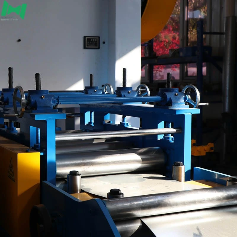
An 8-roller leveler (φ90 mm rollers, 4 kW) flattens the strip. Immediately downstream, the servo pitch feeder delivers it to the press at the exact die-stroke position — eliminating blank-length drift between the leveler and the shear. As a result, length tolerance holds at ±1 mm without operator intervention.
3. 180T Press — Punch + Shear
The 180-tonne mechanical press stamps the hole pattern via the customer-defined die and shears the blank in one stroke. Consequently, hole registration and cut length stay in sync without a separate feeder adjustment.
4. Heavy Conveyor — 4-Metre Powered Table
The 4-metre roller table (1.5 kW, 0.75 kW open/close) carries the blank from press to mill with buffer. Additionally, the heavier table handles 2.0 mm blanks at 600 mm base width without flex or bounce.
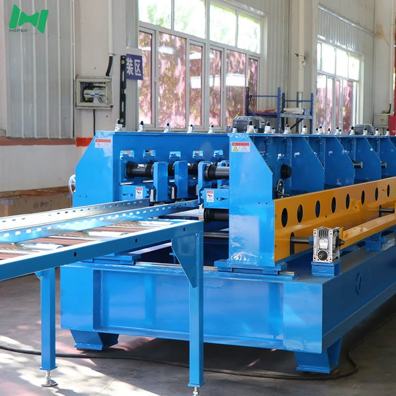
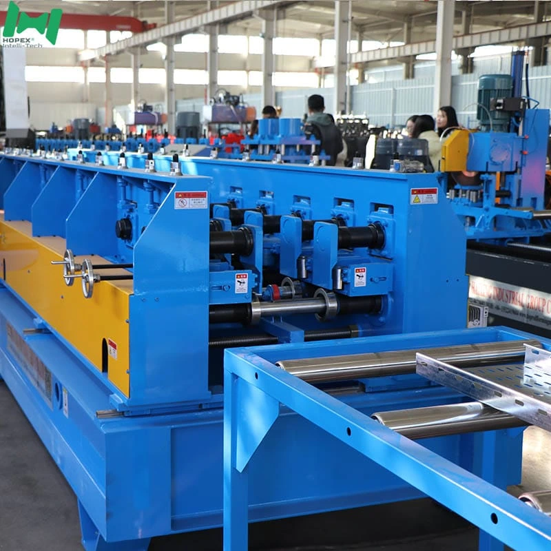
5. Roll Forming Mill — 25 Passes on φ65 mm Shaft
Twenty-five passes on the φ65 mm shaft with a single 5.5 kW main motor and Cr12 HRC58-62 rollers form the profile in progressive stages. Width preset is handled by the 1.5 kW open/close motor from the HMI.
6. Run-Out Platform + Hydraulic Station
A 3-metre passive idler run-out discharges finished trays cleanly. An independent 5.5 kW hydraulic station with a 300 L oil tank feeds the press, shear and decoiler mandrel — sized for 8–12 m/min running without thermal build-up.
Sourced Component Brands
Named parts. Therefore, spares for this cable tray production line are locally sourceable worldwide.
Note: brands listed cover main equipment. Auxiliary parts may vary by production batch; substitutions are disclosed at order confirmation.
Where This Cable Tray Production Line Fits Best
Because it covers six standard sizes on a 40 kW single-motor line, this equipment suits factories optimising for operating efficiency, not just nameplate throughput:
Common Questions
Why only one main motor on a 25-pass mill?
Twenty-five passes spread the forming load progressively, so peak torque at any station is moderate. Furthermore, the φ65 mm through-shaft distributes load evenly along the mill length. As a result, a single 5.5 kW motor is sufficient — and one motor is simpler to maintain than a triple-motor synchronisation system.
How does this cable tray production line hold ±1 mm at 2.0 mm gauge?
Two components deliver the tolerance: the 8-roller servo leveler (eliminates coil-set stress before the press) and the servo pitch feeder (holds blank position to die-stroke precision). Consequently, the press always sees a flat blank at the right position.
What steel can it run?
Q235B cold-rolled, hot-rolled, and galvanized strip from 0.7 to 2.0 mm thick. Additionally, the 8-roller leveler with φ90 mm rollers flattens hot-rolled coil cleanly before the press — the minimum needed for consistent punch quality on hot-rolled strip.
How many sizes without a mechanical change?
Six standard sizes: 600 × 100, 400 × 100, 300 × 100, 200 × 100, 100 × 100, and 50 × 50 mm. Width changes are a 1.5 kW open/close motor preset on the HMI — no manual shim swaps.
Why a 4-metre conveyor instead of 3 metres?
The 4-metre conveyor provides buffer between the press and mill, allowing both to run at independent cycle rates. Furthermore, at 3000 mm workpiece length it gives the blank room to settle before the mill draws it in. In other words, it is what makes consistent 3-metre tray production reliable on this line.
What is the hydraulic station spec?
5.5 kW station with a 300 L oil tank, multiple solenoid valves, electromagnetic pressure relief and active cooling. At 8–12 m/min, the 300 L tank is sufficient to hold oil temperature across a full shift without a separate chiller.
What is the total footprint and power draw?
40 m long × 1.5 m wide × 1.6 m high, drawing approximately 40 kW installed on 380 V / 50 Hz / 3-phase. The 1.5 m width means this cable tray production line fits along a factory wall in a 40 m bay.
Bottom Line
If your factory needs a cable tray production line that covers six standard sizes from 50 × 50 mm to 600 × 100 mm at ±1 mm tolerance, on 40 kW installed power, with one motor to maintain, this 50-600mm line is built for it. It combines a 6-tonne decoiler, an 8-roller servo leveler, a 180-tonne mechanical press, a 4-metre heavy conveyor, and a 25-pass HRC58-62 mill on a φ65 mm shaft — all inside a 40 × 1.5 × 1.6 m footprint drawing just 40 kW, backed by a 5.5 kW / 300 L hydraulic station.
For die drawings, roller-hardness documentation, or a walk-through of the six-size HMI changeover, contact our engineering team with your target sizes, hole pattern, steel grade and monthly output. Then we configure the die, rollers and forming setup to your production plan.