
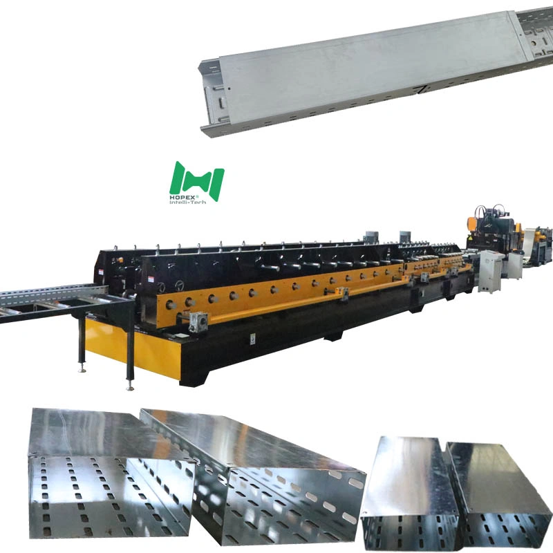
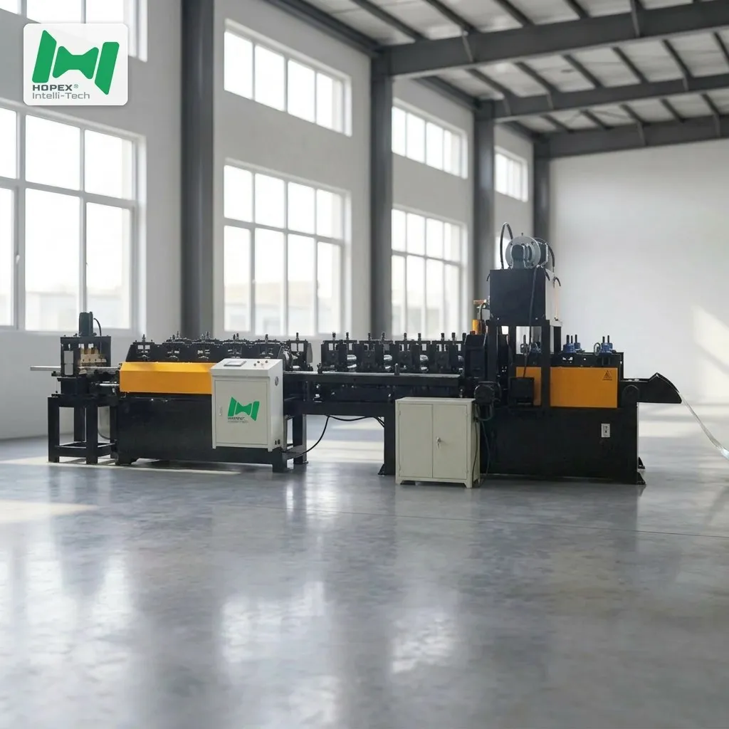
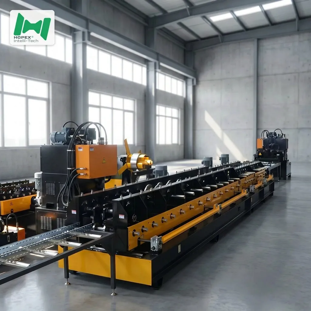
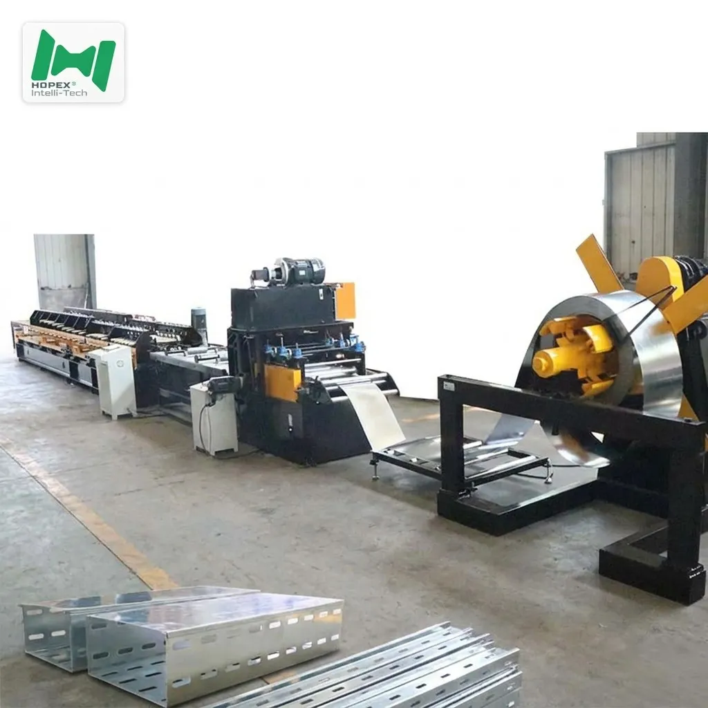
Every tray you sell needs a cover. Yet most manufacturers produce covers on a line built for tray bodies — running 0.6mm cover stock through tooling designed for 1.5mm structural material.
The result is predictable. Edge waviness. Inconsistent lip geometry. Covers that will not seat cleanly on the tray below them. And a heavy line tied up producing a light part.
This cable tray cover roll forming machine is dimensioned specifically for cover production: 101–304mm width, steel at 0.6–0.8mm, aluminium at 0.8mm. Cover gauge, cover width, cover economics.
Why Cover Production Needs Its Own Line
Cover Gauge Is Thin Gauge
Tray bodies carry load and need structural thickness. Covers shed dust and water — they need stiffness, not strength. That is why covers run 0.6–0.8mm while bodies run heavier.
Thin gauge is harder to form well, not easier. At 0.6mm every alignment error becomes visible surface waviness, and spring-back behaviour turns unpredictable. A cable tray cover roll forming machine has to be built around that reality rather than adapted to it.
Cover Width Tracks Tray Width
Covers are sized to the trays they close. The 101–304mm range on this line covers the light commercial and equipment-room tray sizes that dominate most order books.
Fit Tolerance Is Unforgiving
A cover that is 2mm out of specification does not fit. There is no adjustment on site — the installer either seats it or sets it aside. Dimensional repeatability is not a quality preference here, it is a functional requirement.
Machine Configuration
Main Forming Unit
Control System
Hydraulic System
Drive System
Decoiler
Run-Out Table
Finished Cover Capability
Tooling Built for Thin-Gauge Accuracy
Cover profiles live or die on roller condition. A worn roller rounds off the return lip, and a rounded lip means the cover no longer grips the tray edge.
Cr12 hardened to HRC 58–62 holds that lip geometry through long production life. The 45-steel shafts at HRC 28–32 take the opposite treatment deliberately — a shaft hardened to roller specification would be brittle under chain-drive shock loading. Both components are machined to specification first, then heat treated.
Five Reasons This Line Suits Cover Production
1. Five-Roller Leveling Before Any Forming
Coil stock holds curvature from winding. The 2-upper / 3-lower leveling set erases that memory before the strip reaches forming tooling. On 0.6mm cover stock this step is decisive — residual coil set that would vanish in heavy gauge shows up as visible waviness across a cover’s flat top surface.
2. Twenty-Two Stations for Gentle Deformation
Cover profiles are simple compared with tray bodies, but simple does not mean easy at thin gauge. Distributing the bend across 22 stations keeps deformation per station small, which is what prevents cracked edges and unpredictable spring-back.
3. Dedicated Straightening Before Cutting
Four-roller axial straightening removes residual twist and camber. Over a 7–8 meter steel cover, small angular deviation compounds into visible bow — and a bowed cover does not seat.
4. Both Materials, One Line
Steel at 0.6–0.8mm for standard commercial work, aluminium at 0.8mm where weight or corrosion resistance matters. Serving both markets requires no second line.
5. Long Covers, Fewer Joints
Steel covers at 7–8 meters mean fewer joints along an installed run. Fewer joints mean faster covering, fewer clips, and a cleaner finished appearance — the part of your product the client actually sees.
Production Sequence
- Decoiling — 3-ton hydraulic expansion mandrel, coils to 1600mm outer diameter, 460–520mm inner diameter
- Guided Infeed — guide shaft and guide roller establish lateral position before forming
- Leveling — 2-upper / 3-lower roller set removes coil set and residual curvature
- Hydraulic Punching — ventilation perforation applied; punch density governs line speed
- 22-Station Roll Forming — progressive forming, chain-driven by 4 kW × 2 motors through Ruibofeng reducers
- 4-Roller Axial Straightening — final geometry correction
- Rear-Insert Cutting — cut-to-length with 5–6mm scrap cut-off for clean square ends
- Run-Out — two 3-meter roller tables support the finished cover
Control Architecture
A XinJe PLC coordinates the sequence, INVT drivers govern motor output, and a XinJe Electric touch screen carries the operator interface. A length encoder reports actual strip travel, so cuts trigger on measured length rather than elapsed time — accuracy holds across 4-meter aluminium and 7–8 meter steel alike.
The external jog controller is a working tool rather than a specification-sheet entry. During threading, die changes, and commissioning, an operator inches the line from the point of work while watching the strip. Without it, threading becomes a two-person task.
Component Sourcing
Established industrial brands with mature service networks — spare parts and technical support stay accessible across the machine’s service life.
Frequently Asked Questions
Why run covers on a separate line instead of the tray body line? Gauge mismatch. Tray bodies need structural thickness; covers run 0.6–0.8mm. Tooling sized for heavy gauge does not hold accuracy on thin stock, and a heavy line producing light parts ties up capacity you need elsewhere.
Does this machine produce ventilated covers? Hydraulic punching is part of the configuration, so perforated covers are within scope. Punch density directly affects line speed within the stated 3–5 meter per minute range.
Why is aluminium limited to 4 meters when steel reaches 7–8? Aluminium at 0.8mm is less stiff than steel at the same gauge. Shorter lengths stay rigid enough to handle and stack without permanent deformation.
What coil sizes does the decoiler accept? Up to 1600mm outer diameter with 460–520mm inner diameter, at 3 tons maximum. Expansion is hydraulic, which holds constant grip as the coil unwinds.
Why does the cutting station generate scrap? The 5–6mm scrap cut-off removes the deformed edge that shearing creates, so the finished cover and the next piece both exit with clean square ends — no deburring before packing.
Discuss Your Cover Production Requirements
Send your cover width range, material gauge, perforation pattern, and target output volume. Our engineering team will confirm the configuration and realistic throughput for your specification.