
Gantry Cable Tray Forming Machine 50-300mm
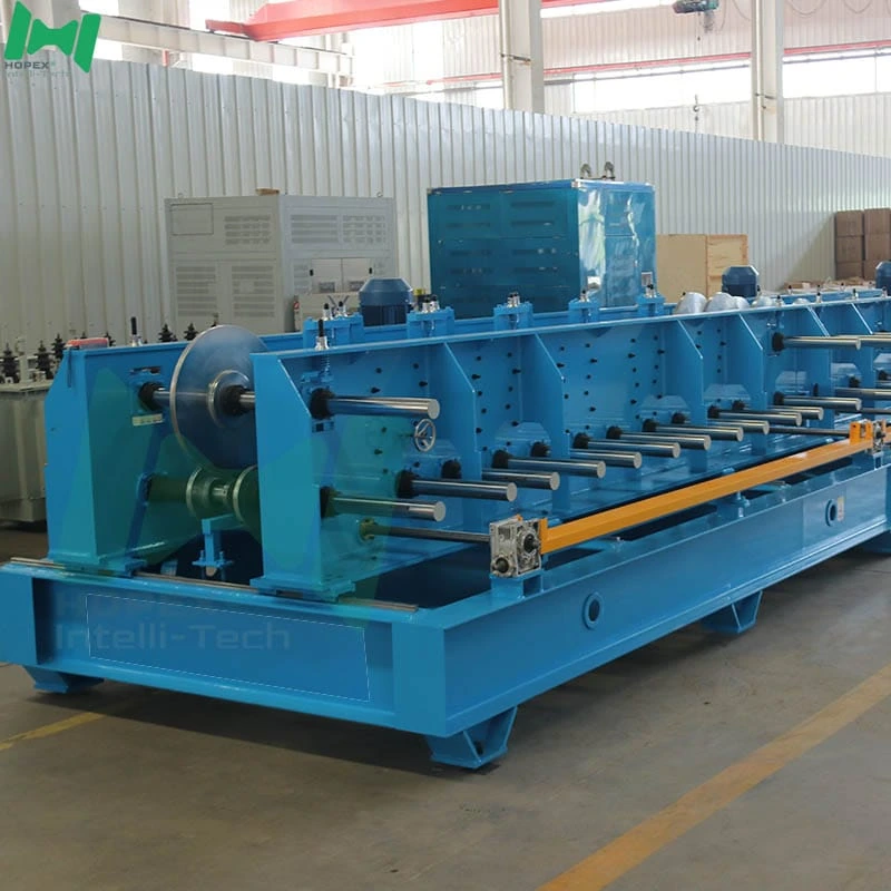
Rigid gantry cable tray forming machine producing 50–300 mm × 50 mm double arc edge cable trays across a 28-pass through-shaft mill. Each φ50 mm forming shaft is supported at both ends — not cantilevered — so wall angle and edge geometry hold across a full production shift. Combines a 5-tonne hydraulic decoiler, 11-roller precision leveler with servo feeding, 180-tonne Hebei mechanical press, and twin 5.5 kW main drives — all inside a 30 × 2.5 × 2.2 m footprint drawing 50 kW installed. Built for factories where tray-to-tray consistency is not negotiable.
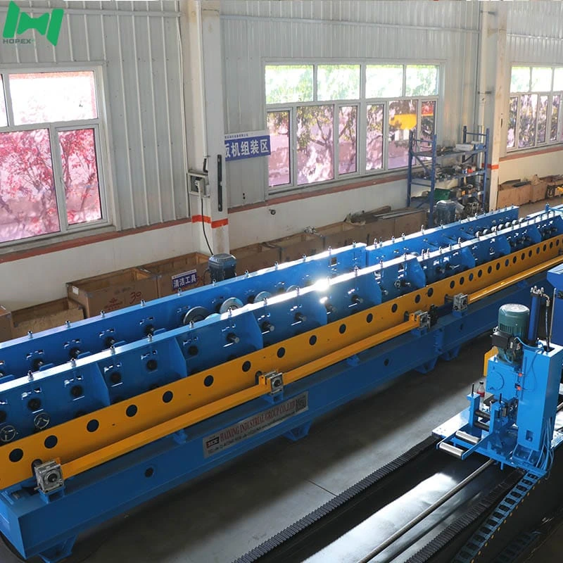
Looking for a gantry cable tray forming machine built around a rigid through-shaft frame, not a cantilevered side-plate mill? This 50–300 mm line delivers exactly that. Moreover, its gantry-style bridge structure carries the 28-pass forming mill on φ50 mm shafts supported at both ends — not overhung — so 1.5 mm strip forms into a double arc edge without wall-angle drift across a full production shift.
The line is engineered around a 180-tonne Hebei mechanical press, an 11-roller precision leveler with servo feeding, and a 28-pass forming mill on φ50 mm 45# steel through-shafts driven by twin 5.5 kW main motors. Consequently, it produces smooth-edged, dimensionally consistent cable trays across the 50–300 mm width band at 5–12 m/min in Q235 cold-rolled or galvanized strip. In short, this is the equipment specification factories reach for when tolerance drift over a full shift is not acceptable.
What “Gantry” Means on a Cable Tray Forming Machine
The word gets used loosely in roll-forming marketing. Here it means something specific: the mill frame is a rigid bridge (gantry) that supports each shaft at both ends — versus a cantilever mill where one end of each shaft is free-hanging off a side plate. Notably, three practical consequences follow:
1. Shaft Deflection Stays Low Across the Width
At 300 mm base width and 1.5 mm strip, the middle of the shaft carries the highest forming load. However, on a cantilever mill the free end drops fractionally under that load, twisting the roller and producing wall-angle drift on wide profiles. Furthermore, a gantry frame supports both ends of the shaft, so deflection stays within microns even at full width.
2. Tolerance Holds Over the Full Shift
Cantilever mills accumulate wear at the free-end bearing faster than the fixed-end bearing. As a result, tolerance drifts over the shift as one side wears while the other holds. Additionally, a through-shaft gantry mill wears symmetrically on both bearings, so the ±1.5 mm length-and-width tolerance and 90° ± 2° angle spec hold from the first tray to the last.
3. Roller Changeover Is Predictable
Because both ends of the shaft are accessible via matched bearing housings, replacing a worn roller is a symmetric operation. Consequently, changeover time between size settings is repeatable, and re-centering after roller swaps is minimal.
Gantry Cable Tray Forming Machine at a Glance
Through-Shaft Explained — Why It Matters on a 28-Pass Cable Tray Forming Machine
A through-shaft mill supports each forming shaft on two bearings, one at each end. In contrast, a half-shaft or cantilever mill carries each shaft on one bearing plus a free end. Furthermore, the more forming passes a mill runs, the more the difference matters — because accumulated deflection compounds pass by pass.
This gantry cable tray forming machine runs 28 passes on through-shafts, which matters for one specific reason: the double arc edge is a compound curve, not a single fold. Consequently, forming the arc cleanly requires progressive small-angle bends across many stations — and each station must present the strip to the next at a repeatable position. Any drift from shaft deflection multiplies across 28 passes and shows up as edge waviness on the finished tray.
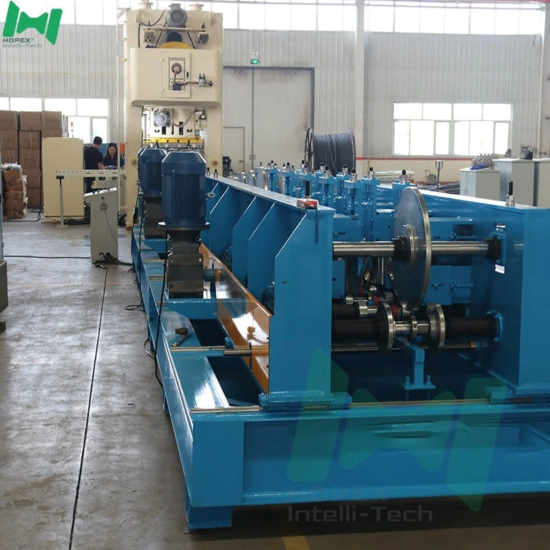
Additionally, the through-shaft design allows the mill’s chain drive to run centreline under the shafts, which balances torque delivery across both ends of the shaft. Consequently, twist between the drive end and the free end is eliminated — a documented failure mode on long cantilever mills.
Why 28 Forming Passes for a Double Arc Edge
Most cable tray lines run 22 to 26 forming passes for a single-fold side edge. However, this line runs 28 — a deliberately higher pass count driven by the geometry of the double arc profile:
- The double arc is two curves, not one bend. Each curve needs its own progressive station sequence.
- Both curves finish on the outside surface — no stress marks are acceptable because that surface is visible on installed trays.
- The transition between the two curves must roll into a repeatable radius, which takes 2–3 dedicated shaping stations per side.
As a result, 6 additional passes (beyond the 22-pass standard) are what produce a clean, symmetrical double arc edge at production speed. Furthermore, cutting stations short to save mill length would show up as edge chatter on 1.5 mm strip — the failure mode is well-documented on undersized mills.
Full Line Walk-Through
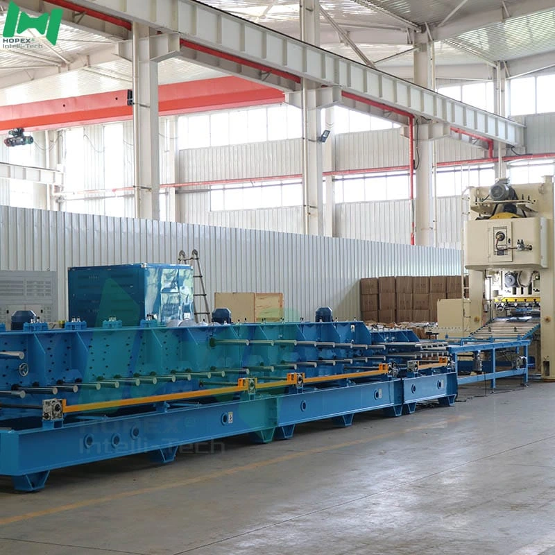
The line reads left to right in seven stations:
5-tonne decoiler → 11-roller leveler + servo feeder → 180T Hebei press (punch + shear) → 3m high-speed conveyor → 28-pass gantry forming mill → 3m run-out
1. Hydraulic Decoiler — 5-Tonne
The coil sits on a hydraulic expanding mandrel with electric drive. Inner diameter opens from φ460 to φ520 mm; outer diameter accepts up to φ1500 mm. Because expansion is hydraulic, coil changes take minutes rather than a manual tightening cycle.
2. Leveling + Punching + Cut-Off Combo
An 11-roller leveler (3 upper, 4 lower, plus one clamp pair at each end) with φ100 mm rollers and 4 kW motor flattens the strip. Furthermore, the servo feeder delivers the strip to the press at the exact stroke position the combination die requires — so hole pattern and cut length stay perfectly registered.
3. 180T Hebei Press — Custom Die
A Hebei-made 180-tonne mechanical press stamps the ventilation or connection hole pattern via a customer-defined die. Additionally, mechanical presses at 180 T are the right choice at 1.5 mm gauge with dense hole layouts — inline hydraulic punching struggles to keep pattern density and edge quality at production speed.
4. Custom Die — Swappable
The die is the swappable heart of the punching station. Consequently, switching to a different hole pattern, spacing or shape means changing the die — not the line. Common patterns include slotted vents, round holes and end connection holes.
5. High-Speed Conveyor — 3-Metre Powered
A 3-metre roller conveyor (1.5 kW main, electric open/close) moves the sheared blank from press to mill. Because it decouples press cycle from mill cycle, a slower forming pass does not delay the press.
6. Gantry Forming Mill — 28 Passes on φ50 mm Through-Shafts
Twenty-eight forming passes on φ50 mm 45# steel through-shafts progressively roll the double arc edge and finish the tray profile. Twin 5.5 kW main motors drive the chain, and two 1.5 kW motors handle automatic open/close for width preset changes. Rollers are Cr12 tool steel.
7. Run-Out Platform
A 3-metre passive idler run-out carries finished trays for pick-up. Because it is passive, discharge is clean and the tray surface is not marked by drive rollers.
Gantry Cable Tray Forming Machine — Sourced Component Brands
Named parts. Therefore, spares for this gantry cable tray forming machine are locally sourceable worldwide.
Note: brands listed cover main equipment. Auxiliary parts may vary by production batch; substitutions are disclosed at order confirmation.
Gantry Frame vs Cantilever — The Practical Split
If you are choosing between this gantry mill and a cantilevered small-tray line, here is the practical split:
In other words, if trays need to look and measure the same at the end of the shift as at the start, the gantry frame architecture is the decision that makes it possible.
Where a Gantry Cable Tray Forming Machine Earns Its Keep
Because the gantry frame holds tolerance across full shifts, this line suits fabricators serving projects where tray consistency matters:
The Double Arc Edge — Why the Profile Choice Matters
Most cable trays fold the side wall into a single sharp flange. However, the double arc edge rolls that flange into two smooth curves — one at the top of the wall, one folding under. Furthermore, three things change on the jobsite:
- Safer handling. Electricians grip the edge dozens of times per shift. Consequently, a rolled-under double arc removes cuts and glove wear.
- Higher torsional stiffness. Two curves stiffen the side wall more than a single fold. As a result, the tray resists twist over long cable runs.
- Cleaner look on exposed runs. In spaces such as data halls, retail ceilings and open-plan offices, the rounded lip installs cleaner than a raw flange.
In other words, you get a tray that is safer to install, stronger in service, and more presentable when the ceiling stays open.
Common Questions
What makes this a “gantry” cable tray forming machine?
The mill frame is a rigid bridge (gantry) that supports each forming shaft at both ends. Furthermore, this contrasts with cantilever mills, where each shaft is carried on one bearing plus a free end. As a result, shaft deflection under load stays minimal even at 300 mm base width and 1.5 mm strip.
Why does through-shaft matter over 28 passes on a cable tray forming machine?
The double arc edge is a compound curve, and any drift from shaft deflection multiplies pass by pass across 28 stations. Consequently, through-shafts (supported at both ends) keep every station presenting the strip at a repeatable position — critical for a clean edge without stress marks.
Is the double arc edge purely cosmetic?
No. In addition to a cleaner look on exposed runs, the double arc stiffens the wall against twist and eliminates the sharp lip that cuts installer hands. Notably, all three benefits show up in daily field use, not just at the specification stage.
What is the actual production speed?
5–12 metres per minute, depending on tray length and hole count per tray. Denser hole patterns pull speed toward 5 m/min because the press cycle governs; sparse patterns run near 12 m/min.
How many widths can I run without a mechanical change?
The mill’s 50–300 mm width range covers the full standard commercial tray envelope. Additionally, width preset changes are handled by the 1.5 kW × 2 automatic open/close motors — moving between 50, 100, 150, 200 and 300 mm trays is an HMI recipe call, not a mechanical strip-down.
Why 180 T press instead of a smaller one?
At 1.5 mm gauge with dense hole layouts, 180 tonnes is the right tonnage class to punch and shear in one stroke without stress marks. Furthermore, a 120 T press would require sequential partial-stroke punching, which introduces registration drift between hole spacing and cut length.
What steel does the line handle?
Q235 cold-rolled and galvanized strip from 0.5 to 1.5 mm thick. Additionally, the strip width band of 150–450 mm covers all base widths from 50 to 300 mm.
What is the total footprint and power draw?
30 m long × 2.5 m wide × 2.2 m high, drawing approximately 50 kW installed on 380 V / 50 Hz / 3-phase. Additionally, a compressed-air supply of 0.5 m³/min at up to 0.7 MPa is required.
Bottom Line
If your production plan calls for double arc edge cable trays across the 50–300 mm width band, made on a mill that holds tolerance across a full shift, this gantry cable tray forming machine is the equipment for it. It combines a 5-tonne hydraulic decoiler, an 11-roller precision leveler with servo feeding, a 180-tonne Hebei mechanical press, and a 28-pass through-shaft forming mill on φ50 mm shafts driven by twin 5.5 kW main motors — all inside a 30 × 2.5 × 2.2 m footprint drawing approximately 50 kW installed.
For die drawings, edge-radius intake, or a walk-through of the gantry cable tray forming machine frame construction, contact our engineering team with your target sizes, hole pattern, steel grade and monthly output. Then we configure the die, small-edge rollers and mill setup to your production plan. production plan. n. production plan. put. Then we configure the die, small-edge rollers and mill setup to your production plan. production plan. n. production plan.