
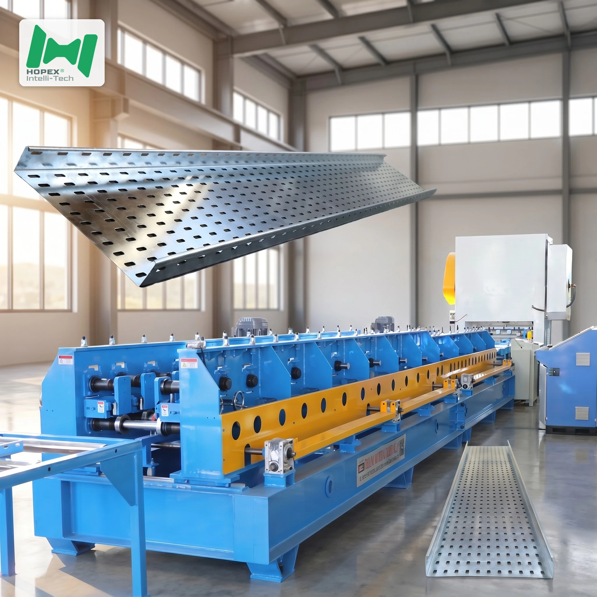
Light Gauge Cable Tray Machine 50-600mm — 1.0 to 1.5mm
High-volume light gauge cable tray machine for commercial-spec cable trays in 1.0–1.5 mm Q235B cold-rolled and galvanized steel. Covers six standard sizes from 50 × 50 mm to 600 × 100 mm, with workpieces up to 6000 mm long. Combines a 200-tonne Yangli press with combination die, 11-roller servo leveler, and 26-pass forming mill on a φ65 mm shaft driven by three 5.5 kW distributed motors — 60 kW installed, 35 × 1.5 × 1.6 m footprint. Built for office, retail, hospital, school and light-industrial commercial cable tray production at scale.
Commercial cable tray work does not need 2.0 mm steel. Moreover, using heavy gauge on a commercial building run adds unnecessary dead load to suspended ceilings, increases hanger counts and raises steel consumption without improving performance. This light gauge cable tray machine is sized for the work that actually makes up most of a cable tray fabricator’s order book: 1.0–1.5 mm Q235B cold-rolled and galvanized trays across the 50–600 mm width range, punched by a 200-tonne Yangli press with a combination die and formed through a 26-pass mill on a φ65 mm shaft driven by three 5.5 kW motors.
The line covers six standard tray sizes from 50 × 50 mm to 600 × 100 mm, holds ±1.5 mm tolerance, and runs at 6–10 m/min with inline hole punching. Furthermore, at 60 kW installed on a 35 × 1.5 × 1.6 m footprint, it is a serious production line — not a light-duty sampler — engineered for high-volume commercial output. In short, it is the equipment specification factories buy when commercial-spec cable trays are their primary product.
Why 1.5mm Is the Right Ceiling for Commercial Trays
Specifiers ordering cable trays for commercial buildings — offices, retail, schools, hospitals, data rooms — rarely specify above 1.5 mm gauge. Furthermore, three engineering and commercial reasons drive that limit:
1. Suspension Load Constraints
Commercial ceilings are typically designed for total suspension loads of 25–50 kg per hanger point, including tray weight, cable fill and safety factor. Specifically, a 600 mm × 100 mm tray at 1.5 mm galvanized weighs approximately 8–9 kg/m empty. Additionally, the same tray at 2.0 mm weighs 10–12 kg/m. As a result, moving to 2.0 mm eats into the hanger load budget without adding cable capacity — particularly critical in renovation projects with existing ceiling structure.
2. Cable Fill, Not Steel Weight, Is the Constraint
IEC 61537 and NEMA VE 1 both define cable fill in terms of cross-sectional area, not tray weight. Consequently, adding steel gauge does not allow more cables — only adding tray width or depth does. Therefore, commercial specifiers choose width and depth first, then specify the minimum gauge that meets the deflection requirement for the chosen span. In most commercial applications, 1.2–1.5 mm achieves the required stiffness without the mass penalty of 2.0 mm.
3. Galvanized Commercial Trays Are Not Structural Members
Commercial cable trays carry cables, not building loads. Furthermore, the support structure (hanger rods, channel, brackets) carries the tray — not the other way around. As a result, the marginal strength of 2.0 mm over 1.5 mm is unused in a correctly designed support system. Consequently, commercial specifiers specify the gauge that achieves the code-required span, which is typically 1.0–1.5 mm.
Light Gauge Cable Tray Machine at a Glance
Six Standard Commercial Sizes
The 50–600 mm width range and 50–100 mm height range covers the six standard sizes that appear on most commercial project cable tray schedules:
Furthermore, the two 1.5 kW automatic open/close motors handle width changes from the HMI. As a result, moving between these six sizes is a stored recipe call — not a mechanical changeover that interrupts production.
Light Gauge Cable Tray Machine vs Heavy Gauge Line — Choosing the Right Spec
If you are selecting between this light gauge cable tray machine and a heavier-gauge 2.0 mm line for the same floor space, the decision comes down to order-book profile:
In other words, if 80 % or more of your order book is commercial-spec 1.5 mm and below, this line keeps your roller tooling in better condition and your production rhythm consistent — without paying the capital and maintenance overhead of a 2.0 mm heavy-gauge capability you rarely use.
Why the Yangli 200T Press at 1.5mm Gauge
A 200-tonne press for 1.5 mm strip may seem over-specified. However, three factors make the press tonnage a precision choice, not an overbuilt one:
1. Combination Die Requires Full Tonnage on Thick Patterns
The combination die stamps the full hole pattern plus the cut-off in one stroke. Furthermore, at 1.5 mm with a dense hole layout, the total punching force across all holes in the die can approach or exceed 150 tonnes on a wide tray. Consequently, 200T is the right tonnage class to stamp cleanly without partial strokes that distort hole edges.
2. Yangli Build Quality Holds Press Speed
Yangli presses are built for sustained industrial-speed operation. Additionally, at 6–10 m/min line speed the press cycles many times per shift — and press frame rigidity determines whether hole diameter stays consistent across a shift or drifts as the frame fatigues. Furthermore, Yangli’s documented press life at this tonnage class is measured in decades, not years.
3. Press Tonnage Reserve Protects the Die
Running a 180T press at 160T effective punching load wears the die faster than running a 200T press at the same load. As a result, the 200T Yangli press gives the combination die better clearance above its rated punching load — extending die service life and reducing regrind frequency.
Full Line Walk-Through
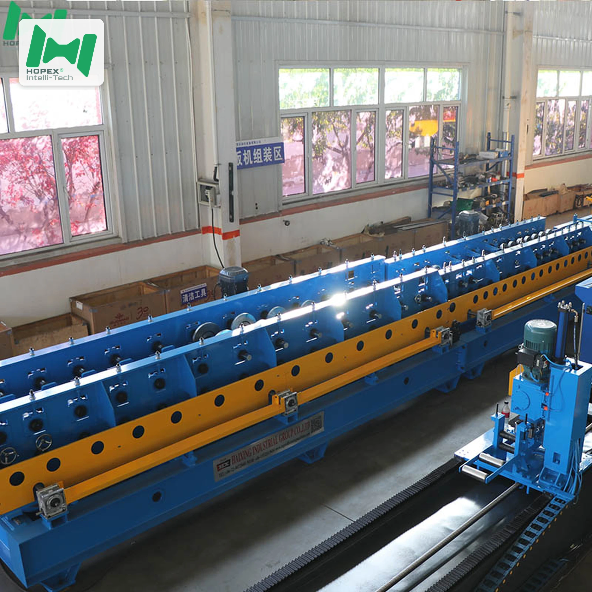
The line reads left to right in six stations:
6-tonne decoiler → 11-roller leveler + servo feeder → 200T Yangli press (combination die) → 3m conveyor → 26-pass forming mill → 3m run-out
1. Decoiler — 6-Tonne Hydraulic
Hydraulic expanding mandrel with electric drive. Inner diameter opens from φ460 to φ520 mm; outer diameter accepts up to φ1600 mm; strip width intake 200–900 mm. Because payoff is powered, even thin 1.0 mm coil pays out under controlled tension without necking or buckling.
2. Leveling + Servo Feeding — 11 Rollers
The 11-roller leveler (3 upper, 4 lower, 2 clamp pairs) with φ100 mm rollers and 4 kW motor flattens the strip. Furthermore, the servo feeder advances the strip to the press at the exact die-stroke position. Consequently, hole-pattern registration and cut length hold at ±1.5 mm across the full shift — critical for 6000 mm tray production where a 1 mm length error per piece accumulates to 10 mm across a 6-tray run.
3. 200T Yangli Press — Combination Die
The Yangli 200-tonne mechanical press closes the combination die in one stroke: punching the ventilation hole pattern and shearing the blank simultaneously. As a result, hole-to-cut registration is die-set, not accumulated by feeder repeat cycles.
4. Conveyor — 3-Metre Powered
A 3-metre roller conveyor (1.5 kW main, 0.37 kW electric open/close) carries the pre-punched blank to the mill. Because it decouples press and mill cycle, press efficiency is not compromised by a slower forming pass.
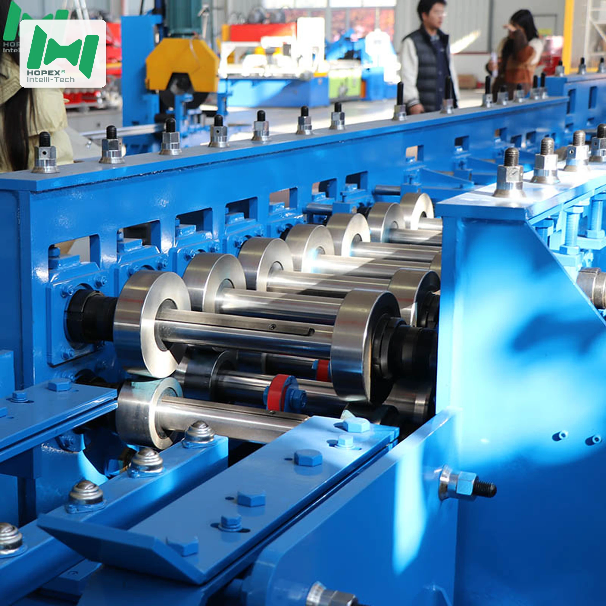
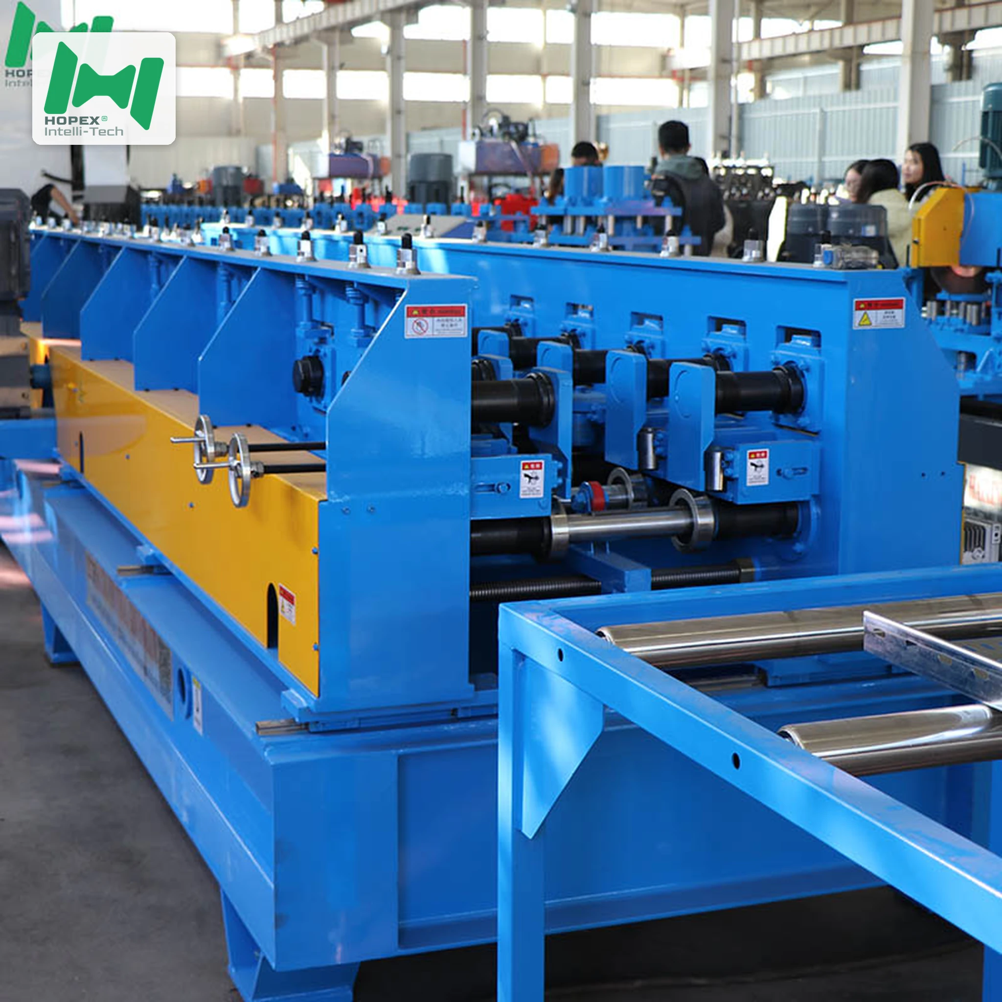
5. Roll Forming Mill — 26 Passes on φ65 mm Shaft
Twenty-six forming passes on the φ65 mm 45# steel shaft form the profile. At 1.0–1.5 mm gauge, 26 passes produce a clean, stress-free profile without the wall-angle spring-back that shorter-pass mills produce on thin strip. Rollers are Cr12 tool steel, and drive is distributed across three 5.5 kW main motors plus two 1.5 kW open/close motors.
6. Run-Out Platform
A 3-metre passive idler run-out discharges finished trays cleanly without drive-roller surface marks.
Sourced Component Brands
Named parts. Therefore, spares for this light gauge cable tray machine are locally sourceable worldwide.
Note: brands listed cover main equipment. Auxiliary parts may vary by production batch; substitutions are disclosed at order confirmation.
Where This Light Gauge Cable Tray Machine Fits Best
Because it is optimised for 1.0–1.5 mm commercial-spec production, this line suits fabricators with a commercial project pipeline:
Common Questions
Why does this light gauge cable tray machine top out at 1.5mm and not 2.0mm?
This line is optimised for commercial-spec production, where 1.5 mm is the standard upper limit. Furthermore, the roller tooling, die clearances and forming pass geometry are set for the 1.0–1.5 mm band — not calibrated for 2.0 mm, which would require different roller clearances and potentially more forming passes at greater wall height. Consequently, running 2.0 mm is not recommended and not supported by the line spec.
Why a 200T press for 1.5mm strip?
As explained in the press section: combination die total punching load, Yangli sustained-speed build quality, and die-life protection all make 200T the correct size. Furthermore, a 160T or 180T press at the same hole density and strip width would run close to its rated capacity — reducing press life and die consistency.
What is the production speed?
6–10 m/min, governed by the press cycle and hole density. Additionally, at 6000 mm workpiece length, the line produces approximately 6–10 complete trays per minute at the fastest hole pattern. Consequently, daily output on a single shift is several hundred trays across the standard commercial size range.
Can this machine produce 6000mm long trays?
Yes. The 6000 mm workpiece capability is standard — not a special configuration. Furthermore, 6-metre trays are specified on commercial corridor runs and riser routes where continuous tray spans reduce installation joints.
What hole patterns can it produce?
The pattern lives entirely in the combination die. Therefore, slotted ventilation holes, round holes, oblong holes and end-connection holes are all achievable — changing the pattern means changing the die, not the line.
What is the total footprint and power draw?
35 m long × 1.5 m wide × 1.6 m high, drawing approximately 60 kW installed on 380 V / 50 Hz / 3-phase. The 1.5 m width means this light gauge cable tray machine fits along a factory wall in a 35 m bay.
Bottom Line
If your production plan calls for high-volume, commercial-spec cable trays at 1.0–1.5 mm gauge across six standard sizes from 50 × 50 mm to 600 × 100 mm, this light gauge cable tray machine is the right line. It combines a 6-tonne decoiler, an 11-roller servo leveler, a 200-tonne Yangli press with combination die, and a 26-pass forming mill on a φ65 mm shaft driven by three 5.5 kW distributed motors — all inside a 35 × 1.5 × 1.6 m footprint drawing approximately 60 kW installed.
For die drawings, hole-pattern intake, or a walk-through of the six-size HMI changeover on this light gauge cable tray machine, contact our project team with your target sizes, hole layout, steel grade and monthly output. Then we configure the die, rollers and mill setup to your commercial production plan. an.