
Wide Cable Tray Machine 100-800mm
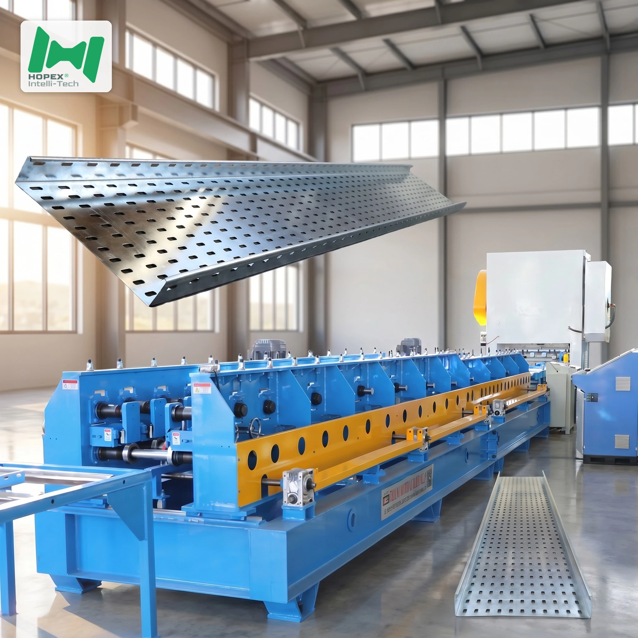
Infrastructure-grade wide cable tray machine for 100–800 mm base × 50–200 mm deep trays in 0.5–2.5 mm Q235 or galvanized steel, up to 10 000 mm long. Designed for tunnel, metro, railway, substation and bridge deck cable management where standard commercial equipment cannot deliver the required width, depth or workpiece length. Features a 10-tonne decoiler, 12-roller leveler, seven-shape punch with integrated shear, 26-pass opposing-roller mill on a φ80 mm through-shaft, dual 6-metre feed tables, and a twin 7.5 kW / 450 L hydraulic station — 65 kW installed, 42 × 2.5 × 1.5 m footprint.
Infrastructure projects — tunnels, metro lines, elevated railways, substations and bridge deck cable runs — do not use the same cable trays as commercial buildings. Moreover, the current volumes, cable bundle sizes, installation spans and structural requirements in these environments push tray specifications to widths, depths and gauges that standard commercial equipment cannot produce. This wide cable tray machine is built for that end of the market: 100–800 mm base width, 50–200 mm side height, 0.5–2.5 mm gauge, workpieces up to 10 000 mm long, with four side reinforcing ribs and two bottom reinforcing ribs formed in-pass.
The line is built around a twin 7.5 kW hydraulic station with a 450 L tank, a 12-roller leveler, a 26-pass mill on a φ80 mm through-shaft, and a 42-metre gantry footprint drawing 65 kW installed. Consequently, this is the widest, deepest, longest and most structurally capable cable tray production line in the catalogue — the one infrastructure fabricators reach for when the project specification leaves no room for lighter equipment. In short, it is a dedicated wide cable tray machine for projects where tray width is an engineering requirement, not a preference.
Infrastructure Cable Tray — Why Width Scales With Current Volume
In commercial buildings, cable tray widths from 100 to 400 mm cover most installations. However, this wide cable tray machine targets infrastructure projects that carry fundamentally different cable loads — and width scales with current volume for a specific engineering reason.
IEC 61537 and NEMA VE 1 both define cable fill ratios as a fraction of the tray’s usable cross-section. Furthermore, as cable count increases, mutual thermal interference reduces each cable’s current rating. Therefore, rather than stacking cables beyond the fill ratio — which would require derating every cable in the tray — infrastructure designers increase tray width to maintain full cable current ratings across large bundles.
Specifically, three infrastructure categories routinely specify 600–800 mm trays:
As a result, specifiers on these projects select width first — to fit all required cables within the fill ratio — then confirm gauge and depth for the required span capacity.
Wide Cable Tray Machine at a Glance
Tunnel and Metro Projects — The 800mm Case
Tunnels are the most demanding cable tray environment. Furthermore, three constraints specific to tunnel installations push tray specifications beyond what commercial lines can produce:
1. Fire Safety and Cable Separation
Infrastructure fire codes require power, control and communication cables to run in separate trays. As a result, a single tunnel route may have three parallel trays side-by-side — each one needing the width to carry its full cable quota. Consequently, 600–800 mm trays are often specified for the power run even when the absolute cable count might fit in a 400 mm tray, because future-proofing and code separation both require headroom.
2. Long Uninterrupted Cable Runs
Tunnels are designed for minimal intermediate junction boxes. Furthermore, long cable runs require large tray cross-sections to maintain current rating without derating, because the bundle temperature rises over distance without intermediate ventilation. Therefore, 800 mm wide and 200 mm deep trays are specified to keep fill ratios below the thermal derating threshold across a 500-metre tunnel run.
3. Seismic and Structural Load
Many tunnel and metro standards specify cable trays that must survive a seismic event at their installed load. As a result, trays need sufficient structural stiffness — achieved through the combination of width, wall height, gauge and rib geometry — to hold position during ground movement. Consequently, the four-rib side wall and two-rib floor on this wide cable tray machine are the structural features that meet seismic and dead-load requirements.
10-Metre Tray — Why Infrastructure Projects Specify Length
Standard tray production targets 2000–3000 mm workpieces. However, infrastructure projects routinely specify 6–10 metre tray sections — and the engineering reason is consistent across project types:
Every tray-to-tray joint is a potential failure point and a maintenance event. Furthermore, in tunnel and metro environments the joints are hard to access and expensive to inspect. As a result, specifiers minimise joint count by specifying the longest practical tray section the installation crew can handle.
Specifically, 10-metre trays are the standard specification for:
- Railway tunnel power runs — 10-metre sections align with track bay spacing
- Bridge deck cable management — 10-metre sections span full structural bay widths
- Substation yard cable trays — 10-metre runs connect transformer bays without intermediate joints
- Industrial plant overhead runs — warehouse bays and equipment clearances often exactly 10 metres
This wide cable tray machine supports 10 000 mm workpieces via the two 6-metre powered feed tables that carry the long blank from the punch to the mill without sag. Consequently, 10-metre tray production is a standard line configuration, not a special-build option.
Six-Rib Architecture — Structural Engineering in the Profile
On a 800 mm × 200 mm tray at 1.5 mm gauge, structural self-stiffness determines whether the tray holds its shape under full cable load between hangers. Furthermore, without ribs, a 800 mm base width and 200 mm side wall would flex enough to cause visible sag between 1.5-metre hanger points — unacceptable on infrastructure installations where cable position is fixed by design.
This wide cable tray machine forms six structural ribs per tray section:
Furthermore, the opposing-roller final forming stations seat both wall ribs and floor ribs with symmetrical load — eliminating the geometric bias that single-sided final stations produce on wide profiles. Consequently, a 800 × 200 mm tray from this line is dimensionally symmetric, which matters for cover fitment and for seismic performance calculations.
The φ80 mm Through-Shaft — Why Diameter Matters at 800mm Width
Most tray forming mills use φ50 to φ65 mm shafts. However, forming a 200 mm side wall at 2.5 mm gauge into a 800 mm wide profile generates forming loads that would deflect a φ65 mm shaft enough to produce asymmetric rib geometry. Furthermore, shaft deflection at the middle of the span produces a different forming force at the centreline than at the ends — causing the tray profile to deviate from geometry across the width.
A φ80 mm through-shaft on this wide cable tray machine — with both ends fully supported in the gantry frame — eliminates that deflection mode. Additionally, the chain drive runs centreline under the shaft, so torque delivery is balanced across the full 800 mm forming width. Consequently, the tray profile is geometrically consistent from edge to edge, which is what ±1 mm tolerance at 800 mm width actually requires.
Full Line Walk-Through
The line reads left to right in eight stations:
10-tonne decoiler → 12-roller leveler + punch + shear → Cover-plate forming module → Rear mill (26 passes + ribs) → 2 × 6m feed tables → 3m run-out → Twin 7.5 kW hydraulic station
1. Decoiler — 10-Tonne Hydraulic
The coil sits on a hydraulic expanding mandrel, rated for a 10-tonne coil — sized for 2.5 mm strip on a continuous production run without frequent coil changes. Inner diameter opens from φ460 to φ520 mm; outer accepts up to φ1500 mm.
2. Leveling + Punch + Shear — 12-Roller Front End
The 12-roller leveler with lift-linkage flattens 2.5 mm strip through six reverse-bend cycles — enough to remove coil-set stress before the punch. Furthermore, the seven-shape punch (large connection holes and tray-floor ventilation) and hydraulic shear share one frame — punch-to-cut registration is die-set, not feeder-accumulated.
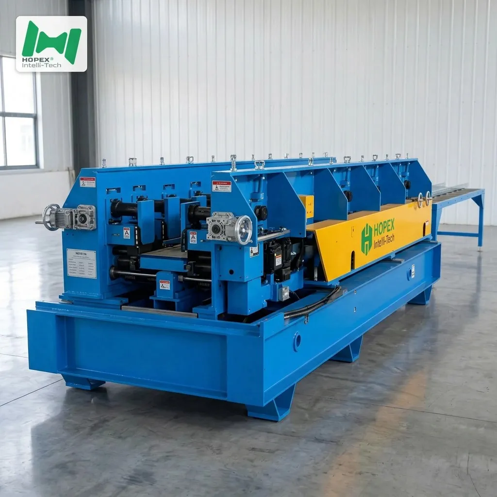
3. Cover-Plate Forming Module
The cover-plate module forms the small edge (8–15 mm), applies small-edge levelling, handles strip guiding and runs the first two side reinforcing ribs. Main motor: 7.5 kW; open/close: 1.5 kW.
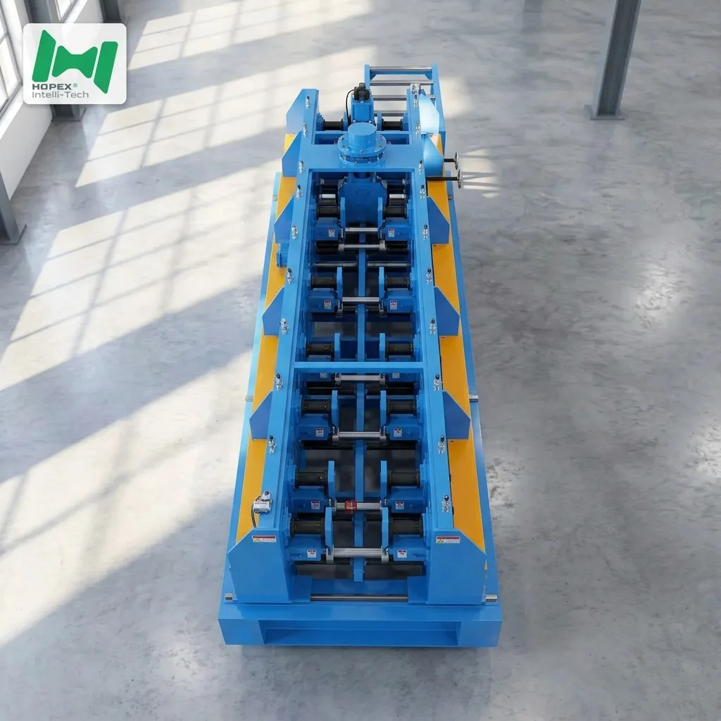
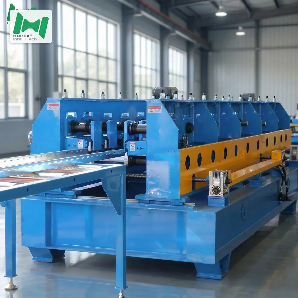
4. Rear Mill — 26 Passes, Opposing Rollers
The rear section forms the wall geometry at 50–200 mm height, finishes the remaining side ribs (2 more per wall) and forms the two floor ribs via opposing-roller geometry. Twin main motors: 7.5 kW × 2; open/close: 1.5 kW.
5. Feed Tables — 2 × 6-Metre Powered
Two 6-metre heavy roller feed tables (1.5 kW × 2) carry 10-metre blanks without sag between punch and mill.
6. Run-Out + Hydraulic Station
A 3-metre passive run-out discharges finished trays. An independent twin 7.5 kW station with 450 L oil tank, three-station valve banks at 220 V, electromagnetic pressure relief and active cooling sustains hydraulic pressure across full 10-metre tray production at 8–16 m/min.
Sourced Component Brands
Named parts. Spares for this wide cable tray machine are therefore locally sourceable worldwide.
Note: brands listed cover main equipment. Auxiliary parts may vary by production batch; substitutions are disclosed at order confirmation.
Where This Wide Cable Tray Machine Earns Its Keep
Because it produces 100–800 mm trays with six structural ribs and 10-metre workpiece capability, this line suits infrastructure-grade fabricators:
Common Questions
What makes this a “wide” cable tray machine versus a standard tray line?
Base widths from 100 to 800 mm — double the 400 mm ceiling of most commercial tray lines. Furthermore, the φ80 mm through-shaft, 12-roller leveler, twin 7.5 kW hydraulic station and six-rib forming architecture are specifically engineered for the load and geometry demands of 800 mm trays at 2.5 mm gauge.
What is the maximum tray size this machine produces?
800 mm base × 200 mm side height × 2.5 mm gauge × 10 000 mm long. As a result, this is the specification that covers the full infrastructure cable tray envelope.
Why does the line draw 65 kW when a commercial line draws 40-60 kW?
The twin 7.5 kW hydraulic station, twin 7.5 kW rear-mill main motors, and the larger 12-roller leveler drive all add to the installed power. Furthermore, 65 kW is what continuous 2.5 mm × 800 mm forming at 8–16 m/min requires without motor thermal derating.
What are the seven-shape punch holes?
The seven-shape hole is the standard connection geometry for steel cable tray joints — a shaped opening that accepts standard connection hardware. Additionally, the line includes optional tray-floor ventilation holes on a separate punch station.
How many trays per shift at 800mm × 200mm × 10m?
At 8 m/min (dense hole pattern), a 10-metre tray takes approximately 75 seconds of forming time plus press cycle. Consequently, a single shift of seven productive hours produces approximately 300+ completed 10-metre tray sections — depending on size mix and hole pattern density.
What is the total footprint and power draw?
42 m long × 2.5 m wide × 1.5 m high, drawing approximately 65 kW installed on 380 V / 50 Hz / 3-phase. Additionally, the twin hydraulic station draws 2 × 7.5 kW with a 450 L oil tank.
Bottom Line
If your production plan covers infrastructure-grade cable trays from 100 to 800 mm wide, 50 to 200 mm deep, at up to 2.5 mm gauge and 10 000 mm long, this wide cable tray machine is the line for it. It combines a 10-tonne decoiler, a 12-roller leveler, a seven-shape punch with integrated shear, a cover-plate forming module, a 26-pass opposing-roller rear mill on a φ80 mm through-shaft, and two 6-metre feed tables — all inside a 42 × 2.5 × 1.5 m footprint drawing 65 kW installed, backed by a twin 7.5 kW hydraulic station with a 450 L oil tank.
For die drawings, seven-shape hole specifications, or seismic-load tray engineering data, contact our project team with your target sizes, hole layout, steel grade and monthly output. Then we configure the punch, ribs and mill to your infrastructure production plan. on plan.