
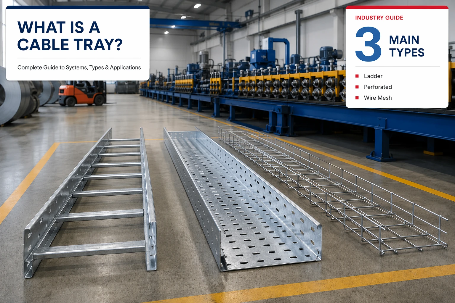
In industrial infrastructure, managing thousands of meters of cabling is a critical challenge. Whether in a data center, chemical plant, or commercial building, the method used to organize power and signal cables impacts safety, longevity, and maintenance costs.
This is where cable tray systems come into play. Described as the “structural backbone” of electrical distribution, cable trays provide a versatile and economical alternative to traditional conduit. This guide provides an overview of technology, materials, and selection criteria for engineers and procurement professionals.
What is a Cable Tray System?
According to the National Electrical Code (NEC), a cable tray system is “a unit or assembly of units or sections and associated fittings forming a rigid structural system used to securely fasten or support cables and raceways.”
Think of cable trays as the roadway bridges of the electrical world. Just as a bridge provides a safe path for vehicle traffic, a cable tray acts as a structural bridge for wires across distances. Unlike enclosed conduits, cable trays offer an open support system allowing for easy access, heat dissipation, and expansion.
Why Choose Cable Tray Systems Over Conduit?
For decades, the industry has favored cable trays for their significant technical and economic advantages:
- Cost Efficiency: Comprehensive studies by the Cable Tray Institute show that cable tray installations can offer labor savings of up to 84% compared to conduit systems. The reduced material footprint also lowers the total cost of ownership.
- Maintenance & Flexibility: Unlike conduits, cables in a tray are accessible for inspection, repair, or replacement. Adding new circuits doesn’t require “fishing” wires through pipes; instead, they are simply laid into the existing structure.
- Heat Dissipation: Open designs allow air to flow freely across the conductors. This prevent excessive heat buildup, which can prematurely age insulation. Properly ventilated systems allow cables to operate at their full free-air ampacity.
- Safety & Environment: Cable trays prevent the accumulation of moisture and flammable gases, which are common risks in enclosed conduit systems. They also provide a clear, visible grounding path for the entire electrical network.
Primary Types of Cable Tray Systems
Selecting the right tray type is crucial for meeting specific mechanical, environmental, and load requirements.
1. Ladder Type Cable Tray
The ladder type cable tray accounts for roughly 75% of all cable tray installations due to its superior strength-to-weight ratio. It consists of two longitudinal side rails connected by transverse rungs spaced at regular intervals.
- Key Advantages: It provides maximum ventilation for high-voltage power cables, effectively dissipating heat. The rungs serve as convenient anchoring points for securing cables with ties—a critical requirement for maintaining circuit integrity during short-circuit fault conditions where magnetic forces can be extreme.
- Applications: Industrial power distribution, oil and gas facilities, and long-span outdoor infrastructure.
2. Single Rail Cable Tray
Constructed from aluminum, the single rail cable tray (center-supported) is designed for speed. It features a central spine with rungs extending on both sides.
- Key Advantages: Quickest installation and maximum freedom for cables to enter or exit from any side.
- Applications: Commercial settings where installation speed is a priority.
3. Fiberglass Cable Tray
In corrosive environments, the fiberglass cable tray (FRP/GRP) is the standard. These are made from glass-reinforced resins.
- Key Advantages: Immune to chemicals and salts, non-conductive, and lightweight.
- Applications: Chemical plants, offshore platforms, and wastewater facilities.
4. Solid Bottom Cable Tray
Used primarily for delicate cables, solid bottom trays provide EMI/RFI shielding when used with covers. They protect cables from falling debris but require careful moisture management.
5. Wire Mesh Cable Tray
Also known as “basket trays,” these are made from welded steel wires. They are easily shaped on-site for complex turns in low-voltage telecommunications and fiber optic applications.
Cable Tray Comparison Table
Selecting the Right Cable Tray: A 5-Step Guide
Follow these steps to ensure compliance and optimal performance:
- Identify the Environment: Assess if the installation is outdoor (requiring Hot-Dip Galvanized or Aluminum), indoor industrial (requiring specific load ratings like the NEMA 200 lb. concentrated load), or a hazardous location involving flammable dust or gases.
- Calculate Load and Fill: Determine the total weight of all cables per linear foot. Refer to NEC Article 392 (Sections 392.9–392.12) for specific fill requirements. Proper fill calculations are essential to prevent over-stacking, which can lead to thermal damage. Always include a 20-30% margin for future expansion.
- Choose Material and Finish: Options include Pre-Galvanized steel (indoor), Hot-Dip Galvanized (outdoor), Stainless Steel (corrosive), or Aluminum (high strength-to-weight).
- Determine Support Spans: The distance between supports dictates the tray “Class.” Longer spans require deeper side rails.
- Select Fittings: Ensure the correct radii for elbows and tees based on the minimum bending radius of the largest cable.
Industry Codes and Standards
Compliance with international standards is essential for project safety:
- NEMA VE 1: Manufacturing requirements for metal cable tray systems.
- NEMA VE 2: Guidelines for shipping, handling, and installation.
- IEC 61537: International standard for cable tray and ladder systems.
- NFPA 70 (NEC Article 392): Governs the safe installation of cable tray systems.
Frequently Asked Questions (FAQs)
Q1: Can I install cable trays in an “Edge-Wise” orientation? A: Yes. There is no NEC limitation preventing vertical orientation, which can minimize dust accumulation in specific locations.
Q2: Is it necessary to ground a cable tray system? A: Yes. Metallic trays can serve as an Equipment Grounding Conductor (EGC) if they are UL-classified and properly bonded.
Q3: Can power and communication cables be in the same tray? A: Only under specific conditions defined by NEC Article 392.20. In most cases, a fixed solid barrier or a separate raceway inside the tray is required. Always verify with the current NEC edition and any local amendments.
Q4: Is walking on cable trays permitted? A: No. It violates NEMA VE 2 safety standards, posing fall hazards and risks to the structural integrity of the system.
Q5: What is the most common rung spacing for ladder trays? A: 9 inches is the industry standard, providing adequate support for most cable sizes.
Technical References
Consult these resources for engineering benchmarks:
- Cable Tray Institute (CTI): Technical bulletins and industry education. www.cabletrays.org
- NEMA Standards: NEMA VE 1 and VE 2. www.nema.org
- IEC 61537: International standard for ladder systems.
- National Electrical Code (NEC): NFPA 70, Article 392.
Conclusion
Understanding cable tray systems is essential for building scalable industrial infrastructure. From the ventilation of a ladder type cable tray to the corrosion resistance of a fiberglass cable tray, the right choice ensures reliability.
As project requirements grow, the need for precision-engineered components becomes critical. Modern manufacturing processes ensure every section meets the load and safety standards required by global industries. Choosing a system that balances material costs with long-term maintenance savings is key to a successful project. a specification is locked, manufacturing precision becomes the next lever. Consistent side-rail geometry, accurate perforation patterns, and stable coating quality are what separate a durable tray run from one that drifts out of alignment on site. HOPEX supports this stage of the value chain by supplying complete cable tray production lines to manufacturers in more than 150 countries, engineered to hold the tolerances specified in NEMA and IEC standards.